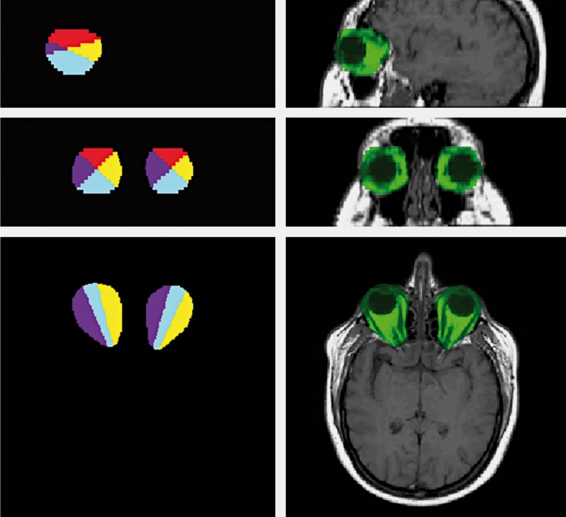
Figure 1.
Example of manually selected ROIs. left, top to bottom: sagittal, coronal and transversal orthogonal cuts of the 3D ROIs, divided into the four quadrants. Right, top to bottom: sagittal, coronal and transversal orthogonal cuts of the 3D ROIs, overlaid on a T1-w image using a simple channel masking method, showing ROI voxels in green.

