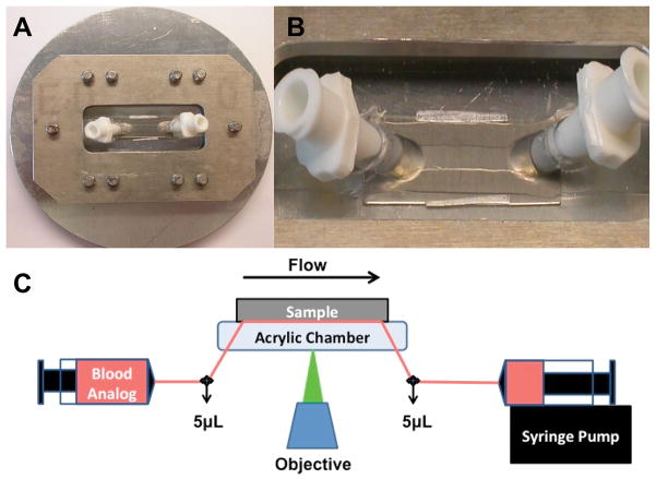
Figure 1.
Parallel plate flow chamber and experimental set up. A) The circular metallic piece and rectangle were secured around the flow chamber with screws. B) The flow path was formed from a silicon gasket. Thin aluminum shim stock can be seen along the length of either side of the silicone gasket to ensure a precise chamber height. C)The blood analogue was perfused through the chamber and across the sample for 5 min. Images were acquired, in real time, 4mm from the inlet by a CCD camera. The transparent blood analogue and long working distance objective allowed for real time visualization of adherent fluorescent platelets through the flow path onto the opaque test surface.

