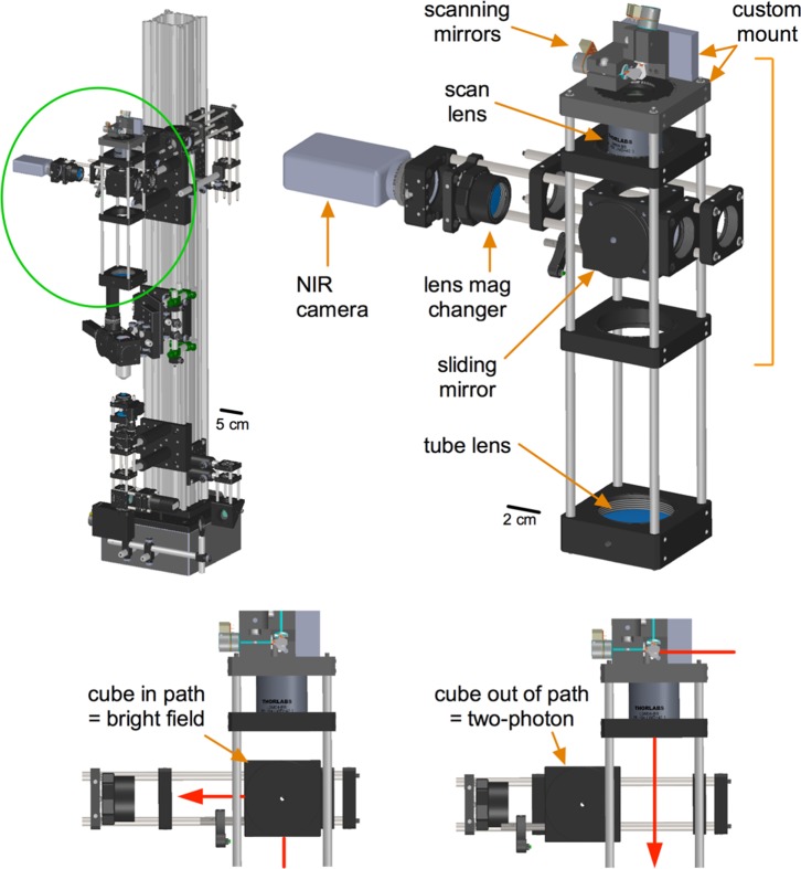
Figure 3. The scanning sub-assembly.
Left) Green circle localizes the scanning sub-assembly on TIMAHC. Right) Main parts of the scanning sub-assembly indicated including: galvanometric scanning mirrors, scan lens, tube lens, sliding cube, lens mag changer and NIR camera. Bottom) Different positions of the sliding mirror cube are shown to select for either two-photon imaging or a LED/camera transmitted image of the sample (see Model S1– scanning sub-assembly).

