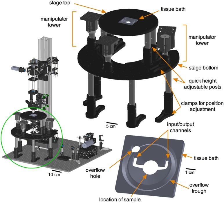
Figure 7. Sample stage sub-assembly.
Left) Green circle localizes the sample stage sub-assembly in relation to TIMAHC. Right) Main parts of the stage sub-assembly are shown including: stage top, stage bottom, tissue bath, height adjustable legs and manipulator towers. Bottom) Close up of tissue bath is shown, highlighting sample compartment, input/output channels, over flow trough and over flow drainage hole (see Model S1– stage sub-assembly).

