Abstract
High-throughput screening (HTS) using multiwell plates and fluorescence plate readers is a powerful tool for drug discovery and evaluation by allowing tens of thousands of assays to be completed in 1 day. Although this method has been successful, electrophoresis-based methods for screening are also of interest to avoid difficulties associated fluorescence assays such as requirements to engineer fluorogenic reactions and false positives. We have developed a method using droplet microfluidics to couple multiwell plate-based assays to microchip electrophoresis (MCE) to screen enzyme modulators. Samples contained in multiwell plates are reformatted in to plugs with a sample volume of 8 nL segmented by an immiscible oil. The segmented flow sample streams are coupled to a hybrid polydimethylsiloxane–glass microfluidic device capable of selectively extracting the aqueous samples from the droplet stream and rapidly analyzing by MCE with laser-induced fluorescence detection. This system was demonstrated by screening a test library of 140 compounds against using protein kinase A. For each sample in the screen, two droplets are generated, allowing approximately 6 MCE injections per sample. Using a 1 s separation at 2000 V/cm, we are able to analyze 96 samples in 12 min. Separation resolution between the internal standard, substrate, and product is 1.2 and average separation efficiency is 16 000 plates/s using real samples. Twenty-five compounds were identified as modulators during primary screening and verified using dose–response curves.
Modern high-throughput screening (HTS) technology allows for 104 to 105 automated assays to be completed in 1 day. HTS has emerged as a powerful tool for many applications including drug, catalyst, and chemical probe discovery. The dominant form of HTS is based on assays performed in multiwell plates (MWP) with liquid handling and plate manipulation performed by robots and detection by optical plate readers. Although this approach has been successful, it has limitations. A fluorescent or other optical indicator must be coupled to or engineered into the biochemical reaction of interest. This requirement can increase development time, reagent costs, and potential for false signals wherein test compounds affect the indicator rather than the actual reaction. Further, in such schemes, only one analyte is detected per reaction and interference from buffer components or test compounds is possible.
Analysis of reaction mixtures by microchip electrophoresis (MCE) can avoid these limitations by separating substrates, products, and interfering species to eliminate the need of having a selective optical change upon reaction. Rapid separations are possible; however, reloading chips with fresh sample is a bottleneck for HTS. A commercial instrument overcomes these problems by “sipping” sample from wells and pulling sample by vacuum into the separation channel.1 This powerful system allows continuous operation and a reliable interface to MWP; however, it does not reach the full potential of MCE because band broadening induced by flow through the separation channel gives reduced resolution requiring longer separation times.
An alternative for screening many distinct samples by MCE is to deliver samples to the chip as droplets or segmented flow.2 In such a method, aqueous samples encapsulated in immiscible oil are pumped into the chip where the aqueous portion is extracted for injection onto the MCE channel. A significant advantage of this approach is that it is also compatible with the emerging trend of miniaturization by performing reactions at droplet scale (pL to nL volume) rather than MWP scale (1–30 μL). Droplet strategies have been used for several novel screens.3−9
Although coupling droplets to MCE is an attractive prospect for HTS, most previous methods of interfacing have been developed for other applications (e.g., for two-dimensional separations10,11 or coupling to a sampling probe for chemical monitoring12−14) and have limited proven utility for screening. Extraction of droplets has relied on modified surface chemistry,2,12,15 applied external fields,16 special channel geometries,10,17 or the use of oleophilic films18,19 to remove carrier oil. In these systems, the extraction and injection processes are coupled so that compromises between droplet size, injection volume, and separation speed must be made. For example, the droplet volume directly controls the injection volume. Often, droplets are larger than typical MCE injection volumes, so separation efficiency is lowered. Also, the droplet flow and manner of extraction can influence the shape of the plug that is loaded onto the separation column, further affecting separation efficiency. An exception was a method that allowed extraction followed by electrokinetic gated injection.15 In this approach, extraction of sample from the oil stream is a separate step from injection so that each is controlled independently. This approach to droplet–MCE interface yielded high efficiency (223 000 plates in 50 s separation); however, it was not shown to be compatible with screening, which requires analysis of many distinct samples and long-term unattended operation of several hundred samples. Further, this method required a complex fabrication procedure involving surface chemistry patterning.
Here we report a new droplet–MCE interface that uses a similar concept of separate extraction and injection. Rather than relying on surface chemistry pattering to achieve injection, the method uses a minor modification of a standard MCE chip design and therefore has a simplified fabrication. We also show that this method allows at least 700 sequential MCE injections from droplet samples with subsecond separations, demonstrating potential for high-throughput screening. We also demonstrate a method to track samples during a screen. The system was tested using a small scale screen of protein kinase A (PKA) modulators but in principle can be applied to any assays resulting in a change in analyte charge or size, such as peptide cleavage, dephosphorylation, and deacetylation.
Experimental Section
Chemicals and Materials
All reagents were purchased from Sigma-Aldrich (St. Louis, MO) with the following exceptions. 5-Carboxyfluorescein (FAM)-labeled Kemptide was purchased from AnaSpec (Fremont, CA) and the catalytic subunit of cAMP-dependent protein kinase A was purchased from New England Biolabs (Ipswich, MA). The epigenetics compound library was purchased from Cayman Chemical (Ann Arbor, MI) and the kinase inhibitor library was obtained from the Center for Chemical Genomics at University of Michigan.
PDMS Chip Fabrication
Polydimethylsiloxane (PDMS) tees were fabricated using a pour over method to align droplet tubing and microfluidic devices during operation. Briefly, a 360 μm o.d. capillary was taped in the bottom of a Petri dish. A 100 o.d. capillary was glued into a 150 μm i.d × 360 o.d. sheath capillary such that ∼3 mm of 100 o.d. capillary was exposed. Two of these sheathed capillaries were taped on opposite sides of the 360 μm o.d. capillary with a 2–3 mm gap between them. PDMS was poured over the mold and cured at 75 °C for 15 min. After curing, the mold was flipped and PDMS was poured on the other side and the mold was cured for an additional 20 min at 75 °C. After curing, all capillaries were removed and the device was cut to size using a razor blade.
Glass Chip Fabrication
Glass chips were fabricated using photolithography and wet-etching by hydrofluoric acid (HF).20−22 Briefly, one slide is etched to 90 μm for the capillary insertion channel and to 50 μm for the sample channel. A second slide is etched to 90 μm for the capillary insertion channel and 5 μm for all separation channels. During etching of deep channels, other features were covered with HF resistant tape (Semiconductor Equipment Corporation, Moorpark, CA). After etching, access holes were drilled with a 500 μm drill bit (Kyocera Tycom, Costa Mesa, CA). Glass slides were washed for 20 min in piranha solution (sulfuric acid:hydrogen peroxide, 4:1) and for 40 min in heated RCA solution (ammonium hydroxide:hydrogen peroxide:water, 1:1:5). Caution!: piranha solution is aggressive and explosive. Never mix piranha waste with solvents. Check the safety precautions before using it. Slides were rinsed with water, aligned under a microscope, and annealed at 610 °C for 8 h. Reservoirs and access ports (IDEX Health and Science, Oak Harbor, WA) were attached at the access holes and a 40 μm i.d. × 150 μm o.d. × 2.5 mm long extraction capillary was waxed in place in the capillary insertion channel.
Microfluidic Chip Operation
All reservoirs and channels on the glass chip were primed with separation buffer (10 mM sodium tetraborate, pH 10, 0.9 mM hydroxypropyl-β-cyclodextran) to remove air bubbles. Voltage for electrophoresis was applied using a CZE1000R power supply (Spellman, Hauppague, NY) and a high-voltage relay (Kilovac, Santa Barbara, CA) was used to control electrokinetic-gated injection.23,24 Detection was accomplished using an in-house confocal laser-induced fluorescence (LIF) detector. Briefly, the 488 nm line from a solid-state laser (CrystaLaser, Reno, NV) was directed through a 488 ± 10 nm band-pass filter and a 10× objective lens. Emission was filtered through a 520 ± 10 nm band-pass filter and detected by a photomultiplier tube (R1477, Hamamatsu, Bridgewater, NJ). Current from the PMT was amplified by a current preamplifier (Stanford Research Systems, Sunnyvale, CA) and monitored using an in-house LabVIEW program (National Instruments, Austin, TX). Data analysis was done using Cutter 7.0,25 Excel 2011 (Microsoft, Redmond, WA), and Igor Pro 6.32 (Wavemetrics, Inc., Lake Oswego, OR).
Droplet Generation from MWP
Droplets, segmented by perfluorinated oil (100:1, perfluorodecalin (PFD):perfluorooctanol (PFO)), were generated from a multiwell plate using a method previously described. Droplet samples were pulled into a 150 μm i.d. × 360 μm o.d. HPFA tube (IDEX Health and Science, Oak Harbor, WA) using a syringe connected to a PHD 200 syringe pump (Harvard Apparatus, Holliston, TX) operating in refilling mode. After the syringe and tubing were primed with 100:1 PFD:PFO, droplets were generated using a computer-controlled XYZ-positioner to move the tubing from well to well in a defined pattern. Samples were covered with carrier oil to prevent sample evaporation and aspiration of air into tubing.8,26
Protein Kinase A Modulator Screen and Droplet Analysis
Each sample in the screen was prepared in 20 μL with final concentrations of 50 mM Tris, pH 7.5; 10 mM MgCl2; 200 μM ATP; 15 μM FAM-Kemptide; 3.75 nM protein kinase A. During screening experiments, test compounds from the kinase inhibitor library were deposited using a Caliper Sciclone (PerkinElmer, Waltham, MA) into a 384-well plate (0.1 to 12.5 μM final concentration). For the epigenetics compound library, compounds were pipetted manually into a 384-well plate (5 μM final concentration). Control samples contained dimethyl sulfoxide (DMSO) at equal volume to test compounds. Negative controls contained no inhibitor (mimicking no inhibition), and positive controls contained no enzyme (mimicking 100% inhibition). Reactions were incubated at room temperature for 30 min and quenched with 80 μL of 15 mM ethylenediaminetetraacetic acid (EDTA) and placed on ice. Immediately prior to droplet generation, 90 μL of each sample was transferred to a modified 384-well plate designed to allow samples to be covered by carrier oil. To extract droplets, a 50 μL syringe filled with water was attached to a 40 μm i.d. × 150 μm o.d. capillary and connected to the PDMS tee after the extraction region and the PDMS chip was primed with water. Next, tubing containing sample droplets was inserted until flush with the extraction capillary in the glass chip and connected to a 100 μL syringe on a syringe pump. Droplets were pumped into the PDMS chip at 360 nL/min and injections were made every 1 s.
Results and Discussion
Droplet Extraction from Segmented Flow
Our strategy for high throughput electrophoresis is to introduce a series of samples to the microchip as segmented flow. A primary challenge of achieving rapid MCE analysis from segmented flow is separation of the oil phase from sample prior to MCE analysis. To simplify the process of droplet extraction, we used the native properties of glass (hydrophilic) and PDMS (hydrophobic) to extract droplets through a hybrid device (Figure 1). An advantage of this approach is that we take advantage of the native surface chemistry of these materials to achieve extraction, eliminating the need for surface patterning. A hybrid device has the added benefit of decoupling the extraction and analysis stages for better performance. Also, it has the practical advantage that a new extraction or analysis chip can be substituted if it stops working without the need to fabricate a new device.
Figure 1.
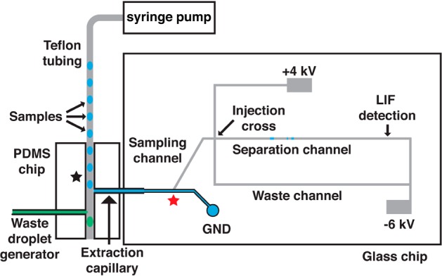
Schematic of PDMS–glass hybrid microfluidic device for analysis of segmented flow samples. Aqueous droplets (blue colored) are extracted by the hydrophilic extraction capillary and sampled by electro-osmotic flow (EOF) in the sampling channel toward the injection cross. During injection, the positive high-voltage power supply is floated to allow injection of a discrete sample plug into the separation channel. The positive high-voltage is applied again during separation and excess sample is gated to the waste channel. To assist extraction waste droplets (green colored) are generated after the extraction point to provide a slight backpressure for extraction.
In this device, a length of Teflon tubing containing sample droplets is positioned orthogonal to the inlet of a fused silica extraction capillary that is interfaced to the glass MCE chip using a tee molded from PDMS (Figure 1). The fused silica extraction capillary also acts as a conduit to the glass MCE chip. As droplets exit the Teflon tubing, aqueous samples are extracted into the hydrophilic fused silica extraction capillary while the oil phase continues toward the outlet of the hydrophobic PDMS device. The extracted sample droplet fills the extraction capillary and sampling channel (Figure 1) where it can be injected onto the MCE channel using an electrokinetic flow gate.23,24 Subsequent samples wash the extraction capillary and sampling channel out for serial injections.
Although the inherent surface chemistry of the extraction capillary and PDMS tee will favor droplet extraction and oil phase flow past the extraction point, it is also necessary to use proper capillary and channel dimensions so that capillary force and back pressure are balanced to favor droplet but not oil flow into the extraction capillary. In other words, with high flow rates, wide bore extraction capillaries or narrow PDMS channels, oil can be forced into the extraction capillary. In the opposite case, aqueous samples will not be fully extracted. For the flow rates and chip dimensions used here, a 40 μm i.d. fused silica capillary generated good extraction (i.e., the entire aqueous droplet) with no oil phase entering the extraction capillary. We visually observed that droplet extraction was more reliable by elevating pressure slightly at the outlet of the PDMS tee. This pressure was created by a pumping water at 150 nL/min into an inlet positioned downstream of the extraction point (waste droplet generator in Figure 1).
The chip was also designed to minimize carryover between samples. To reduce carryover, dead volume from the extraction point on the PDMS device to the sampling point, on the glass device was minimized through the use of narrow bore capillaries and short capillary lengths (3.3 nL). With this small volume, we anticipated that ∼10 nL of sample would be needed to washout the capillary and prevent carryover.
To evaluate the extraction efficiency and sample carryover in the extraction channel, we monitored fluorescence as alternating pairs of 8 nL droplets containing fluorescein at high (6 μM) and low (2 μM) concentrations were pumped through the system. Droplets are detected as square-topped pulses within the Teflon tube (Figure 2A) reflecting signal from fluorescence within the droplet and no signal for the oil. After extraction, the droplets fill the extraction capillary and become continuous phase without pulses between droplets of the same concentration (red trace, Figure 2A). In the transition from high to low concentration, the signal decreases and then stabilizes. The timing of the transition suggests that the sample is 80% washed out by the first droplet and 98% washed out by the time the second droplet is extracted. In the transition from low to high concentration, the signal stabilizes more quickly. These results show that carryover should be minimized using two droplets. The exact volumes required may depend on the sample type being used, e.g., if surface adsorption is greater, more rinses may be required.
Figure 2.
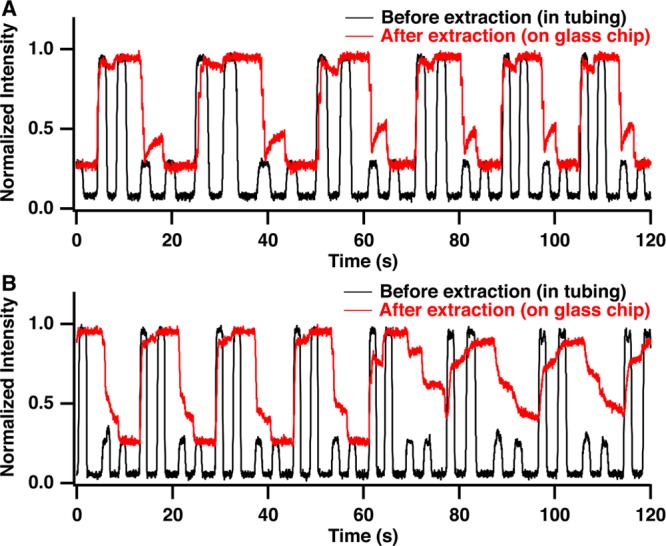
Comparison of extraction of droplet stream with (A) and without (B) waste channel droplets shows the effect of added back pressure on extraction efficiency. When waste droplets are present intensity of droplets before extraction (black trace) is nearly identical to intensity of sample after extraction (red trace) and transitions from high to low intensity occur rapidly suggesting that each droplet rapidly rinses out the previously extracted droplet from the glass chip. Without waste droplets, sample intensity is not stable over time on the MCE chip as sample droplets mix. Detection point for droplets before extraction (black star) and after extraction (red star) are marked on the schematic in Figure 1.
If the back pressure was not provided by the extra flow, the transitions were longer and not as reliable, as shown by the increase in carryover in the red trace in Figure 2B starting after 60 s. This result coincides with incomplete extractions and sample buildup at the capillary inlet. By using the waste droplet to increase pressure in the extraction zone, sampling buildup was greatly reduced and carryover between samples was less than 2% (Figure 2A). At least 500 droplets, the most tested, could be extracted reliably with this approach.
MCE Injection from Droplets
After extraction, aqueous samples fill the sample channel, which acts as the sample reservoir in a cross-style injector in MCE.23,24 In this way, the hybrid chip acts as a means to rapidly introduce new samples to a microfluidic device while maintaining injection geometry known to have high performance.15,23,24,27 To make an injection, sample is directed toward the injection cross by electro-osmotic flow (EOF) using applied electric fields. During separation, this sample stream is gated toward a waste reservoir on chip by a cross-flow, which also provides fresh separation buffer to the electrophoresis channel. During injection, the gating flow is shut off by a high-voltage relay to allow a small plug of sample to be injected into the separation channel for analysis. Importantly, unlike many other designs used for droplet MCE, the volume and shape of the plug that is injected is controlled by the voltages applied independent of the extraction process enabling higher efficiency for a given separation time.
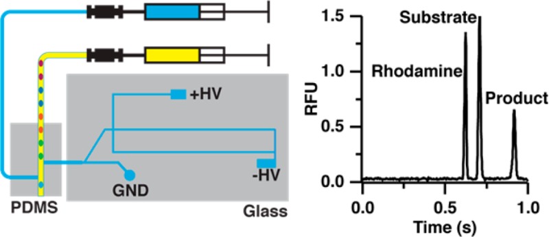
Using this injection method, screening reaction samples containing substrate, product, and rhodamine were separated with good efficiency. For example, using a 10 mM sodium tetraborate buffer at pH 10 and an electric field of 2000 V/cm, separation efficiency of 16 000 plates for a 1 s separation in 0.5 cm was routinely achieved. By making a discrete injection from a larger sample droplet, injection volume is not controlled by droplet volume and multiple injections can be made from each sample droplet. Further, the separation time is not limited by droplet spacing, as is the case when an injection is made from each droplet2,12 or whole droplet injection is used.10 We found that these differences were useful for HTS. Using a gated-injection scheme, coupling MCE to 2D separations or other sampling probes for chemical sensing by segmented flow should also be possible.
Mobility Shift Assay of Enzymatic Reactions
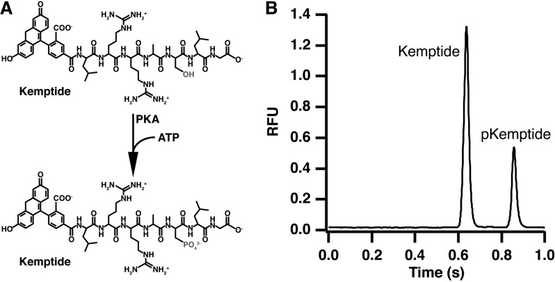
Phosphorylation of kemptide by PKA was used as a test assay for this system (Figure 3A). Injection of the reaction mixture results in two peaks in the electropherogram due to the unphosphorylated substrate and phosphorylated product, which migrates slower due to the addition of a negative charge through the phosphate group (Figure 3B). By injecting substrate alone, only the first peak is present and both substrate and product migration times were verified (data not shown).
Figure 3.
Protein kinase A catalyzed phosphorylation of kemptide (A) and resulting electropherogram (B) for the separation of the reaction mixture. Product and substrate were separated in 0.5 cm using an applied field of 2000 V/cm and a 30 ms injection.
Due to the large number of samples generated in HTS, a rapid MCE separation is required. The change in charge on kemptide due to phosphorylation allowed for easy separation of the substrate and product peak. A separation in <1 s was achieved using a high electric field (2000 V/cm) and a short separation length (0.5 cm) without sacrificing separation resolution. This separation was fast enough to allow at least three injections per droplet that entered the capillary (Figure 4A). Indeed, the effect of droplet clearing can be observed in the relative peak heights for each electropherogram. The first three injections shown in the trace in Figure 4A correspond to the second droplet for a sample and the peak heights are stable. The next four traces correspond to a new sample that has been extracted. Fluctuation in peak height for rhodamine, substrate, and product is observed as the droplet washes out the reservoir and reaches a stable signal, similar to the continuous measurements depicted in Figure 2A. The last three traces correspond to the second droplet being extracted and entering the sample reservoir. By this time, the peak heights have once again stabilized for all traces. Thus, these results illustrate that use of two droplets per sample, the first to rinse the small reservoir and the second to provide a stable signal, allows for analysis of discrete samples in series. In principle, the number of injections per droplet can be varied by using different size droplets and flow rates. Likewise, the amount of rinse required could be decreased by using even lower dead volumes. Obtaining multiple injections per droplet can be valuable in achieving reliable results at the expense of throughput.
Figure 4.
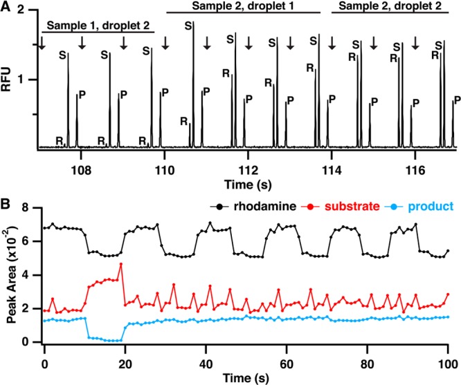
Electropherograms and raw peak area data demonstrating sample clearing and indexing for screening by MCE. (A) Electropherograms showing injection and separation of rhodamine (R), substrate (S), and product (P) and transition from a sample without rhodamine to a sample with rhodamine demonstrating complete sample clearing by two droplets. (B) Extracted peak areas for rhodamine (black trace), substrate (red trace), and product (blue trace) for analysis of 12 samples, two controls and ten test compounds. Changes in rhodamine peak height were used to determine start and end points for each compound to calculate reaction yield.
At this high of a separation speed, reproducibility was still good. For example, we performed over 700 injections in ∼12 min with a migration time relative standard deviation (RSD) of ∼2%. Reaction yield, calculated as P/(P + S), where P and S are the product and substrate peak area respectively, had an RSD of 7% (n = 8) for negative control samples spread throughput the sample set. For a series of injections from a single sample, the RSD was generally less than 5% (n = 3). As observed in the substrate peak area trace in Figure 4B, droplet extraction causes a slight increase in pressure on the glass device, leading to an increase in substrate peak area for that injection. Using reaction yield, instead of raw peak area, for analysis combined with averaging three injections per sample mitigates this effect.
Indexing Droplet Data Using a Fluorescent Dye
When analyzing a series of samples reformatted from a MWP to droplet streams, it can be difficult to determine which electropherograms belong to each sample. This is especially true for the passive extraction/injection system used here. Thus, even though droplets are introduced to the chip at a constant flow rate and injections are performed at a constant rate, we found that the exact number of injections per sample (formatted as two droplets of 8 nL each) can vary from 6 to 8. We attribute this primarily to slight variations in sample size, sample flow rate, and the timing of injection relative to the droplet extraction. The variability in injection number per droplet means that it is necessary to mark each droplet to register an electropherogram with test analyte or sample. Figure 4B illustrates the peak area for a series of electropherograms from assay samples. With the exception of a positive control, which has a low product peak area, determining which data corresponds to each sample is nearly impossible. To avoid this problem, a marker compound, rhodamine 110, was added to every other sample to provide data indexing. During data analysis, every other sample (corresponding to a train of approximately six injections) will have a rhodamine peak in the electropherogram as can be observed in Figure 4A. Using changes in rhodamine intensity as a guide, the start and end point for each sample can be quickly identified across all electropherograms (black trace, Figure 4B). For example, from 20 to 100 s, 10 samples, each containing a different test compound, are analyzed, but substrate and product peak areas remain stable because none of the compounds inhibit PKA. However, utilizing the changes in rhodamine peak area, the change from sample to sample can be tracked.
Droplet-based Screen of Protein Kinase A Modulators
To test our novel droplet–MCE method, we screened two small molecule libraries against PKA for inhibitory activity. The kinase inhibitor library contained 60 test compounds with known activity at various kinases and the epigenetics library contained 80 test compounds that are known to act at proteins involved in histone modification and not necessarily kinases. A total of 168 samples were analyzed for the primary screen, including positive and negative controls. Samples were prepared and reacted as outlined in the Experimental Section and two droplets were generated for each sample. Samples were analyzed in batches of 96 for a total of ∼200 droplets per analysis. Analysis of each batch required approximately 12 min. By generating the next set of samples during analysis, near continuous analysis by MCE is possible, achieving a sample throughput of 0.16 samples/s.
Reaction yields were calculated for each sample and normalized to the average positive control reaction yield (Figure 5). An inhibition threshold was set at 80%, which corresponds to three standard deviations below the normalized positive control yield across all experiments (n = 40). Any compounds with reaction yields below this threshold were identified as inhibitors of PKA with lower reaction yields denoting stronger inhibitors. In total, 25 test compounds (7 from the epigentics library and 18 from the kinase library) were identified as potential hits during the primary screen and all of these compounds showed a dose-dependent inhibition of protein kinase A during follow-up screening experiments. Two false negatives were identified during the screen. One compound, H-89, showed no inhibition at 12.5 μM, but was active at three lower concentrations. The second compound, piceattanol, was present in both compound libraries but was only active in the kinase library. However, a dose-dependent response was observed suggesting this is a true hit compound and was likely degraded in the epignetics compound library. Overall the assays had a high Z′-factor of 0.8, making identification of both strong and weak inhibitors possible.
Figure 5.
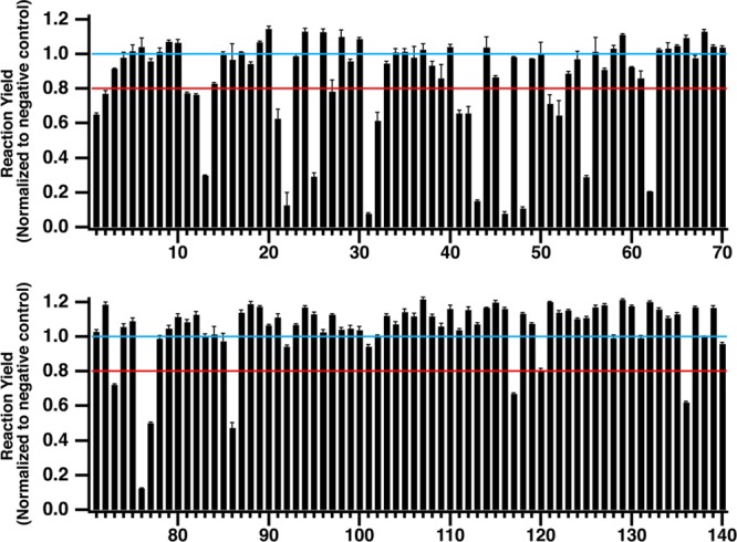
Screening 140 small molecules against protein kinase A reveals 25 hit compounds based on the inhibitor threshold (red line). All reaction yields are normalized to the average negative control yield (blue line). With the exception of compound 25, which is plotted at 2.5 μM, compounds 1–60 were tested at 12.5 μM and compounds 61–140 were tested at 5 μM.
Follow up dose–response curves for H-89 and ellagic acid (Figure 6), two known protein kinase A inhibitors, showed good agreement with accepted IC50 values. For H-89, the experimental IC50 value was 89 ± 1 nM and the IC50 value for ellagic acid was 1.00 ± 0.01 μM. Previous results using filter based assays with [γ-32P]ATP were 135 nM for H-89,28 and 3.5 μM for ellagic acid.29
Figure 6.
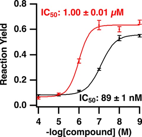
Dose–response curves for H-89 (black trace) and ellagic acid (red trace) generated from protein kinase A screening data. The measured IC50 values agree with literature values of 150 nM28 and 3 μM29 for H-89 and ellagic acid, respectively.
Comparison to Other Systems
It is interesting to consider the potential of this system relative to the commercial MCE screening system described in the introduction. Using a comparable peptide substrate and product, the Caliper instrument was able to analyze samples from multiwell plates using a 42 s separation in a single channel corresponding to 0.02 samples/s.1 In a previous report, we used a droplet extraction method to achieve 0.07 samples/s for one channel.2 The efficiency was much lower than in the new system because the droplet volume and flow rate determined the injection volume. (In a previous report, the same extraction geometry achieved an average separation efficiency of 53 500 plates for a 12 s separation of three amino acid neurotransmitters;12 however, for technical reasons, the efficiency was generally lower for screening purposes.) The droplet MCE system achieves about 10-fold higher sample analysis rates per channel than these prior systems even though replicate injections are performed and some replicates are wasted on carryover. This increase in throughput is due to the higher efficiency enabled by combination of droplet introduction and electrokinetic injection. A further potential advantage of droplet-based sample introduction is a substantial reduction in reagent consumption by utilizing an all-droplet format, i.e., reactions performed in droplets,8,30 which could achieve over a 1000-fold reduction in reagents. Although these observations demonstrate a significant potential advantage of the droplet MCE approach, further testing and development is required before a droplet system could compete with commercial systems in terms of robustness and routine use for screening 104 to 105 samples and continuous operation.
Conclusion
This work has demonstrated a novel droplet extraction method for coupling segmented flow to MCE that uses the native properties of PDMS and glass to separate the two phases in segmented flow prior to electrokinetic injection for MCE. We demonstrated the utility of this sample introduction method combined with MCE for HTS by performing a proof-of-concept screen with PKA and a set 140 small molecules. Each sample consisted of two droplets and approximately six injections were made per sample. This equates to an injection throughput of 1 Hz and a sample throughput of 0.16 Hz, which would allow for analysis of >10 000 samples per day. To increase sample throughput without sacrificing separation resolution or data quality, parallel analysis would be required and could be achieved by fabricated multiple separation channels per device. Additionally, this platform is applicable to other screening assays and other droplet–MCE applications, such as coupling stages of a 2D separation or chemical sensing from sampling probes.
Acknowledgments
This work was supported by NIH grant R01GM102236 and the NIH Microfluidics in Biomedical Sciences Training Program at University of Michigan (T32 EB005582).
The authors declare no competing financial interest.
Funding Statement
National Institutes of Health, United States
References
- Liu Y.; Gerber R.; Wu J.; Tsuruda T.; McCarter J. D. Anal. Biochem. 2008, 378, 53–59. [DOI] [PubMed] [Google Scholar]
- Pei J.; Nie J.; Kennedy R. T. Anal. Chem. 2010, 82, 9261–9267. [DOI] [PubMed] [Google Scholar]
- Küster S. K.; Fagerer S. R.; Verboket P. E.; Eyer K.; Jefimovs K.; Zenobi R.; Dittrich P. S. Anal. Chem. 2013, 85, 1285–1289. [DOI] [PubMed] [Google Scholar]
- Brouzes E.; Medkova M.; Savenelli N.; Marran D.; Twardowski M.; Hutchison J. B.; Rothberg J. M.; Link D. R.; Perrimon N.; Samuels M. L. Proc. Natl. Acad. Sci. U. S. A. 2009, 106, 14195–14200. [DOI] [PMC free article] [PubMed] [Google Scholar]
- He M.; Edgar J. S.; Jeffries G. D. M.; Lorenz R. M.; Shelby J. P.; Chiu D. T. Anal. Chem. 2005, 77, 1539–1544. [DOI] [PubMed] [Google Scholar]
- Song H.; Ismagilov R. F. J. Am. Chem. Soc. 2003, 125, 14613–14619. [DOI] [PMC free article] [PubMed] [Google Scholar]
- Sun M.; Fang Q. Lab Chip 2010, 10, 2864–2868. [DOI] [PubMed] [Google Scholar]
- Sun S.; Slaney T. R.; Kennedy R. T. Anal. Chem. 2012, 84, 5794–5800. [DOI] [PubMed] [Google Scholar]
- Zheng B.; Roach L. S.; Ismagilov R. F. J. Am. Chem. Soc. 2003, 125, 11170–11171. [DOI] [PubMed] [Google Scholar]
- Niu X. Z.; Zhang B.; Marszalek R. T.; Ces O.; Edel J. B.; Klug D. R.; deMello A. J. Chem. Commun. 2009, 6159–6161. [DOI] [PubMed] [Google Scholar]
- Edgar J. S.; Milne G.; Zhao Y.; Pabbati C. P.; Lim D. S. W.; Chiu D. T. Angew. Chem., Int. Ed. 2009, 48, 2719–2722. [DOI] [PMC free article] [PubMed] [Google Scholar]
- Roman G. T.; Wang M.; Shultz K. N.; Jennings C.; Kennedy R. T. Anal. Chem. 2008, 80, 8231–8238. [DOI] [PMC free article] [PubMed] [Google Scholar]
- Slaney T. R.; Nie J.; Hershey N. D.; Thwar P. K.; Linderman J.; Burns M. A.; Kennedy R. T. Anal. Chem. 2011, 83, 5207–5213. [DOI] [PMC free article] [PubMed] [Google Scholar]
- Wang M.; Roman G. T.; Schultz K.; Jennings C.; Kennedy R. T. Anal. Chem. 2008, 80, 5607–5615. [DOI] [PMC free article] [PubMed] [Google Scholar]
- Wang M.; Roman G. T.; Perry M. L.; Kennedy R. T. Anal. Chem. 2009, 81, 9072–9078. [DOI] [PMC free article] [PubMed] [Google Scholar]
- Fidalgo L. M.; Whyte G.; Ruotolo B. T.; Benesch J. L. P.; Stengel F.; Abell C.; Robinson C. V.; Huck W. T. S. Angew. Chem., Int. Ed. 2009, 48, 3665–3668. [DOI] [PubMed] [Google Scholar]
- Angelescu D. E.; Mercier B.; Siess D.; Schroeder R. Anal. Chem. 2010, 82, 2412–2420. [DOI] [PubMed] [Google Scholar]
- Niu X.; Pereira F.; Edel J. B.; de Mello A. J. Anal. Chem. 2013, 85, 8654–8660. [DOI] [PubMed] [Google Scholar]
- Pereira F.; Niu X.; deMello A. J. PLoS One 2013, 8, e63087. [DOI] [PMC free article] [PubMed] [Google Scholar]
- Harrison D. J.; Fluri K.; Seiler K.; Fan Z.; Effenhauser C. S.; Manz A. Science 1993, 261, 895–897. [DOI] [PubMed] [Google Scholar]
- Roper M. G.; Shackman J. G.; Dahlgren G. M.; Kennedy R. T. Anal. Chem. 2003, 75, 4711–4717. [DOI] [PubMed] [Google Scholar]
- Simpson P. C.; Roach D.; Woolley A. T.; Thorsen T.; Johnston R.; Sensabaugh G. F.; Mathies R. A. Proc. Natl. Acad. Sci. U. S. A. 1998, 95, 2256–2261. [DOI] [PMC free article] [PubMed] [Google Scholar]
- Jacobson S. C.; Hergenroder R.; Moore A. W. Jr.; Ramsey J. M. Anal. Chem. 1994, 66, 4127–4132. [Google Scholar]
- Jacobson S. C.; Koutny L. B.; Hergenroeder R.; Moore A. W.; Ramsey J. M. Anal. Chem. 1994, 66, 3472–3476. [Google Scholar]
- Shackman J. G.; Watson C. J.; Kennedy R. T. J. Chromatogr. A 2004, 1040, 273–282. [DOI] [PubMed] [Google Scholar]
- Pei J.; Li Q.; Lee M. S.; Valaskovic G. A.; Kennedy R. T. Anal. Chem. 2009, 81, 6558–6561. [DOI] [PMC free article] [PubMed] [Google Scholar]
- Culbertson C. T.; Jacobson S. C.; Ramsey J. M. Anal. Chem. 2000, 72, 5814–5819. [DOI] [PubMed] [Google Scholar]
- Davies S. P.; Reddy H.; Caivano M.; Cohen P. Biochem. J. 2000, 351, 95–105. [DOI] [PMC free article] [PubMed] [Google Scholar]
- Cozza G.; Bonvini P.; Zorzi E.; Poletto G.; Pagano M. A.; Sarno S.; Donella-Deana A.; Zagotto G.; Rosolen A.; Pinna L. A.; Meggio F.; Moro S. J. Med. Chem. 2006, 49, 2363–2366. [DOI] [PubMed] [Google Scholar]
- Miller O. J.; Harrak A. E.; Mangeat T.; Baret J.-C.; Frenz L.; Debs B. E.; Mayot E.; Samuels M. L.; Rooney E. K.; Dieu P.; Galvan M.; Link D. R.; Griffiths A. D. Proc. Natl. Acad. Sci. U. S. A. 2012, 109, 378–383. [DOI] [PMC free article] [PubMed] [Google Scholar]


