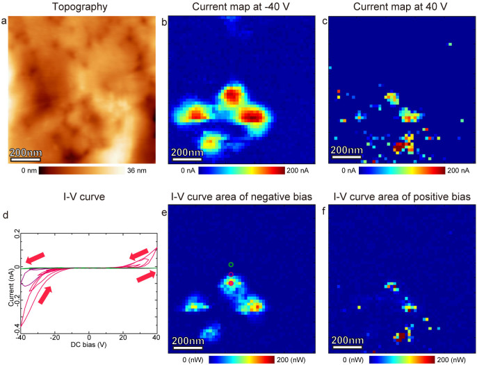
Figure 7. I-V loop opening at the conductive points.
Current maps and spatial maps of I-V loop area simultaneously obtained with Fig. 5 and Fig. 6. (a) topographic image of the measured region. (b) Current map at −40 V. (c) Current map at 40 V. (d) Individual I-V loops extracted from the encircled point in e. (e) I-V loop area map calculated for negative branch of I-V loop. (f) I-V loop area map calculated for positive branch of I-V loop.

