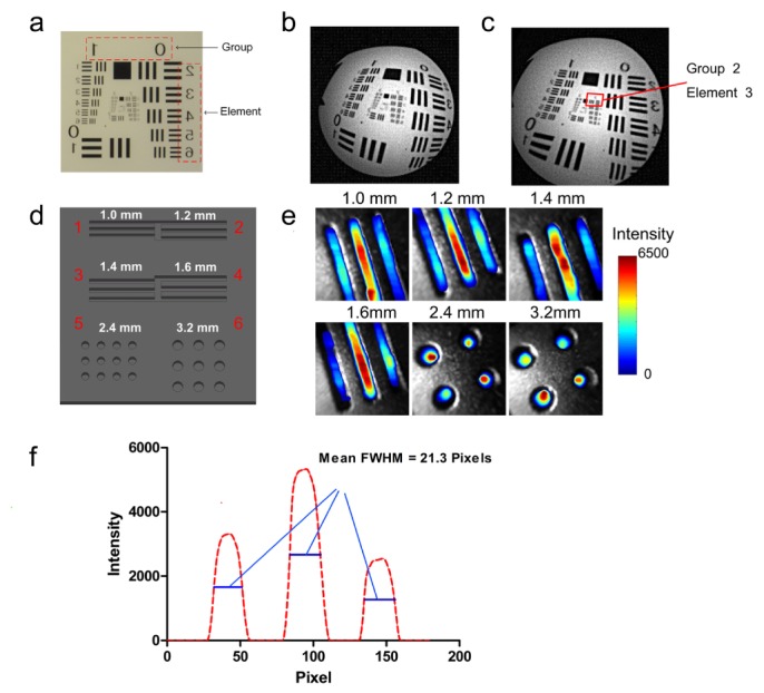
Fig. 3.

Results of the spatial lateral resolution evaluation experiment. (a) Photograph of the 1951 USAF test board; (b) Photographic image acquired by the ECLI system; (c) Calibrated image of (b); (d) Sketch of the homemade test board used in the CL resolution evaluation experiment; (e) Fusion images of each area in the test chart; (f) Quantitative line profile (red line in area 1).
