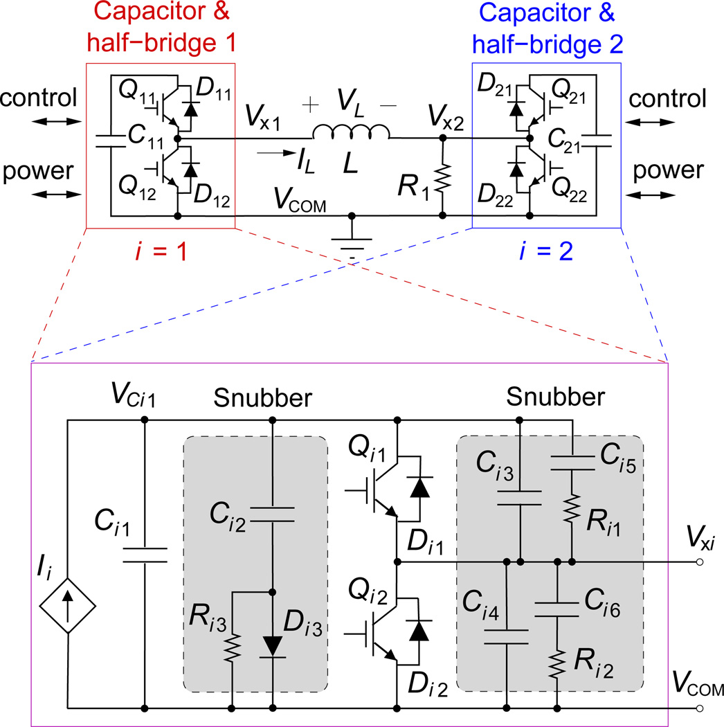
Figure 1.
Diagram of key elements of the cTMS3 circuit. (top) Two half-bridges connected to energy storage capacitors (i = 1,2) drive differentially the stimulation coil L. (bottom) Each half-bridge, Qi1/Di1 − Qi2/Di2, is connected to an energy-storage capacitor Ci1 and charge control module Ii. Passive snubber circuits are shown in shaded blocks.

