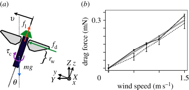
Figure 3.

Model for the lateral planar dynamics of the robotic fly. (a) The vehicle state is given by three quantities: the attitude angle θ, the angular velocity  and the lateral velocity v (given in body-attached coordinates). A lift force fl generated by the flapping wings acts at a distance rw away from the CM and along the body z-direction, an aerodynamic drag force fd acts at a distance rw from the CM, and the gravitational force mg acts at the CM. The right-handed axis convention for world coordinates is shown in the inset, with x pointing into the paper; lowercase letters denote body-frame coordinates and capital letters denote world-frame coordinates. A feedback controller applies a control torque τc by altering baseline wing kinematics. (b) Wind tunnel tests of a flapping-wing robotic fly indicate that aerodynamic drag is roughly proportional to wind speed for wind from the front (+x-direction, solid line) and from the side (+y-direction, dashed) for typical wing kinematics. Force measurements (mean ± s.d.) were taken using a torque sensor (Nano 17, ATI Industrial Automation, Apex, NC, USA) on a 30 cm cantilever arm. The slope of the linear fit for both cases, bw, was modelled as equivalent for both directions and is shown as a thick line and given in table 1. (Reproduced with permission from [34].) (Online version in colour.)
