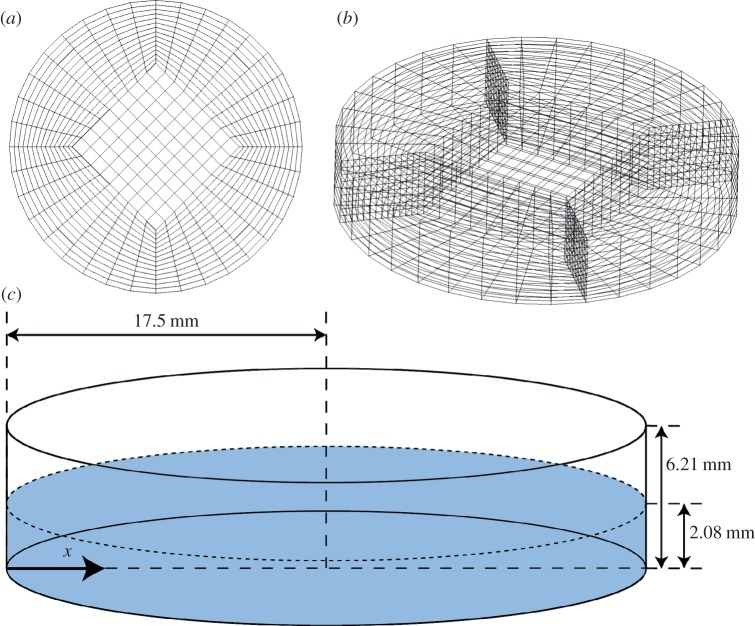
Figure 1.
(a) Graphical representation of a butterfly mesh; (b) vertical extrusion of butterfly mesh by 6.21 mm creates the grid used for CFD modelling; (c) schematic showing model dimensions and the x-coordinate system used for analysis. The plane defined by the dashed circumference is the initial free surface boundary, as specified in the volume of fluid method [14].

