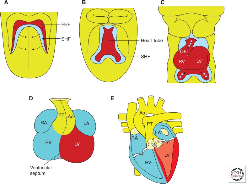
Figure 2.
Graphical representation of murine heart development. (A) Embryonic day (E) 7.75–8.0 showing relationship between progenitors of the first heart field (FHF; red) and second heart field (SHF; blue). Arrows indicate the direction of convergence of progenitors during heart tube formation. (B) E8.0–8.5 showing the linear heart tube derived largely from the FHF with SHF progenitors persisting dorsal to the heart tube. (C) E9.5 and (D) E12.5, showing looped hearts. Arrows and dots in C indicate deployment of SHF cells to the growing poles of the heart. Colors in D indicate approximate origins of chamber cardiomyocytes from FHF and SHF progenitor cells. (E) Late embryonic/postnatal stages, showing final heart structure. Ao, aorta; LA, left atrium; LV, left ventricle; PT, pulmonary tract; RA, right atrium; RV, right ventricle. (Adapted, with permission, from Cohen et al. 2008.)

