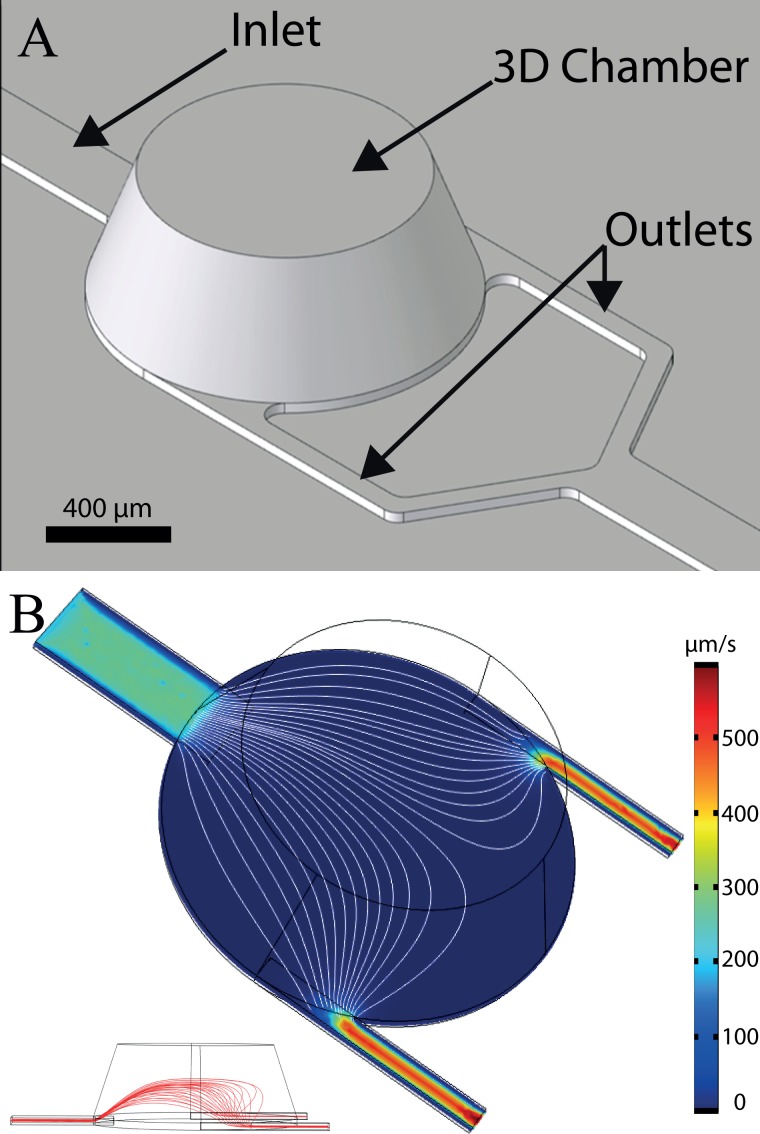
FIG. 3.
(a) Virtual image of the 3D chip design. The chamber has a tapered profile with an inner diameter ranging from1 mm diameter at the bottom down to 750 μm diameter on top and a height of 350 μm. Channels have a width of 200 μm for the inlet and 60 μm for outlets. The channel's height is 30 μm. (b) 3D simulation of the flow velocity distribution at 15 μm from the surface, inside chamber, and channels. The mean flow velocity is higher in the channels as compared to the chamber area. Furthermore, the flow velocity distribution in the horizontal plan is relatively homogenous across the chamber (streamline density). Streamlines show the laminar flow inside the chamber (white line). On the bottom left inset, a side cross section view of the chip showing the vertical development of streamlines is provided.

