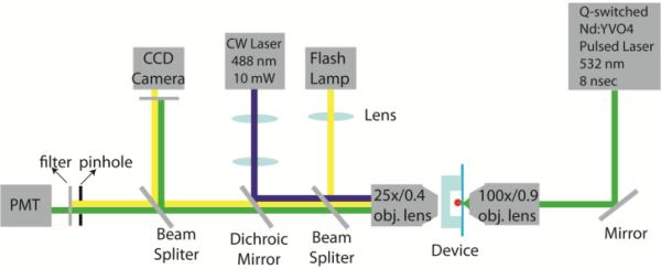
Fig. 3.
Experimental setup. A Q-switched Nd: YVO4 pulsed laser was focused into the middle of the bubble channel through a 100×/N.A. 0.9 objective lens. CW laser at 488 nm was used for fluorescence excitation through a 25×/N.A. 0.4 objective lens. The emission fluorescence was collected by the same objective lens and detected by a photomultiplier tube (PMT) which connected to a DAQ card for signal acquisition and processing. FPGA logic was programmed using Labview to perform real-time detection, threshold comparison, and timed triggering of the pulsed laser. To observe and characterize the bubble, a flash lamp was used to capture time-resolved images on a CCD camera.

