
Figure 1.
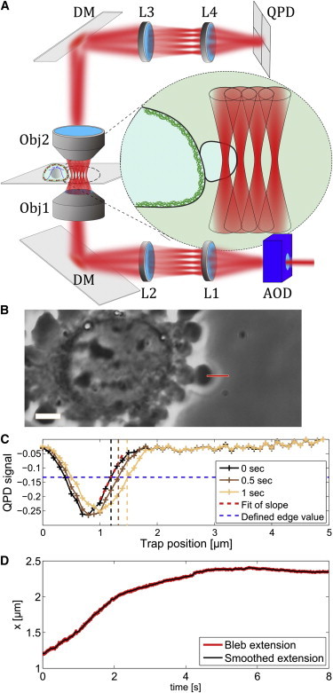
Experimental procedure: (A) sketch of the setup, where the laser position is controlled by an acousto-optical deflector (AOD) and imaged in the back focal plane of the objective 1 (Obj1) via a telescope formed by the lenses L1 (f = 15 cm) and L2 (f = 30 cm) and the dichroic mirror (DM). After interaction with the bleb (see inset) the light is collected by the objective 2 (Obj2) and the back focal plane of Obj2 is imaged to the QPD via L3 (f = 9 cm) and L4 (f = 4.5 cm). (B) Example of the experimental procedure, where a bleb is identified and the position and direction of the scan line is controlled by the experimenter via a custom-programmed user interface (LABVIEW; National Instruments, Austin, TX). Scale bar, 5 μm. (C) Example of three scan results at different time-points. The edge position is defined by the first scan and used in the following sequence to determine the edge movement. (D) Measured time evolution of the bleb membrane during bleb growth and arrest.