
Fig. 4.
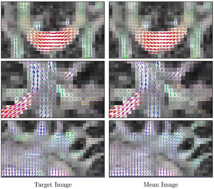
ODFs in the regions marked by yellow rectangles in Fig. 3. The target anisotropy image is used as the background. (For interpretation of the references to color in this figure legend, the reader is referred to the web version of this article.)