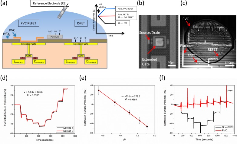
Figure 1.
Device schematic and characterization (a) A FET/REFET device schematic is shown. Two fluid gate methods are included: A pH-insensitive reference electrode and a pH-sensitive on-chip platinum electrode. PVC covers the left ISFET, rendering it insensitive to pH changes. The right ISFET is left uncovered and is sensitive to pH. The inset plot shows theoretical device response to a hydrogen addition event. The Pt vs FET and RE vs REFET show no overall response to pH changes. Whereas the Pt vs REFET and RE vs FET show opposite responses. Further details are found in Supporting Information Figure S2. (b) An extended gate ISFET is shown. The sensing region consists of a layer of hafnium oxide on a metal extended gate. (c) One microliter of PVC is spotted on some of the devices to render them pH insensitive, but still functional. (d) A real-time pH response curve of two untreated ISFETs comprising four additions of NaOH followed by four additions of HCl. The response closely matches the Nernstian response for ISFET gate dielectrics with an average pH response of 54 mV/pH and R2 linearity of 0.995. (e) Quantification of the HCl addition steps for multiple devices is shown (n = 16). (f) Real-time response curve for a RE vs FET (black) and a RE vs PVC REFET (red). The PVC-treated device shows minimal pH response over the duration of the test.

