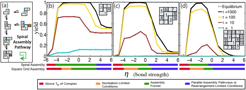
Figure 6. Design of components so that particular assembly pathways are favored can drastically increase assembly yields.

(a) Schematic of spiral complex assembly via the favored assembly pathway. On the favored assembly pathway, assembly begins with the “L” shaped component, labeled “1”. At each assembly step, a component attaches through two interfaces (following the green arrow). Other components can only attach through one. Lengths of reaction arrows indicate propensities in the assembly funnel regime. Assembly yields for a (b) 2×2 (4 component), (c) 3×3 (9 component) and (d) 4×4 (16 component) spiral complex as a function of a dimensionless temperature parameter,  . Inset diagram depicts the complex and numbers on the components in the complex indicate component identity. Colored bars below the figure represent the four different assembly regimes for spiral complexes and grid complexes containing the same number of components. Error bars <1%.
