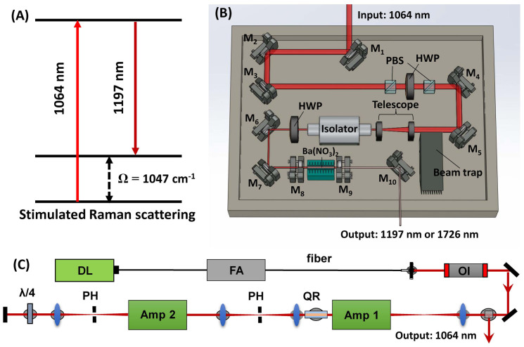
Figure 1. Principles and schematics of the Raman laser system.
(A) The principle of the Ba(NO3)2 crystal-based Raman Shifter. (B) The Schematics of the Raman shifter: M1-M7: 45° 1064 nm reflective mirror; PBS: polarizing beam splitter; HWP: half wave plate; M8: resonator end mirror; M9: output coupler; M10: silver mirror. (C) The schematics of the MOPA system: Amp: amplifier; PH: pin hole; QR: quartz rotator; OI: optical isolator; FA: fiber amplifier; DL: Directly modulated diode laser.

