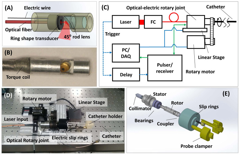
Figure 3.
Schematics of the IVPA system: Schematic (A) and photograph (B) of the IVPA probe. (C) Block diagram showing the data acquisition system. FC: fiber coupler; PC/DAQ: personal computer, data acquisition. (D) Photograph of the scanning assembly. (E) Schematic of the assembly of optical rotary joint and electrical slip rings.

