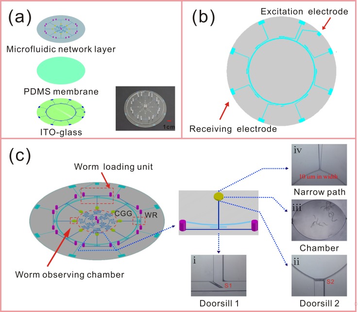
FIG. 1.
Schematics and photographs of the microfluidic platform for manganese toxicity assessment and rescue assay. (a) The structure of the chip is composed of three layers, the microfluidic network layer, thin PDMS membrane (100 μm in thickness), and ITO-glass. The inset is a photograph of the fabricated microfluidic chip. (b) The layout of the ITO electrodes for worm responder. (c) Schematics of the microfluidic chip. Our chip contains the structures of CGG and eight uniform loading units which are composed of eight T-shape channels and eight ellipse observing chambers. There are four functional units: worm loading units, worm observing chambers, CGG, and worm responders (WRs), which have been highlighted using red dashed outline. The magnified photomicrographs of the unique components, (i) doorsill S1 (in the cross-sectional area of T-shape channel), (ii) doorsill S2 (before the ellipse observing chamber), (iii) the chamber within 20 worms, and (iv) a narrow path (at the exit of the observing chamber) have been located in the schematics.

