
Figure 5.
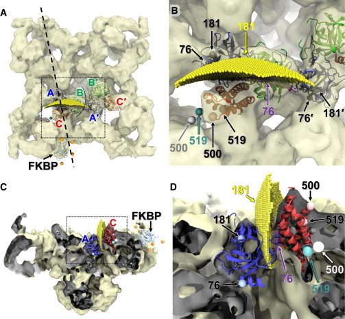
Trilaterated loci of Cy3NTA acceptors attached to His10 tags in the RyR1 N-terminal domain. (A) RyR1 is viewed from cytosolic side. Trilaterated acceptor positions are shown for His10 inserted at positions 76 (purple) and 181 (yellow) in the A-domain (blue), and at positions 500 (gray sphere) and 519 (cyan sphere) in the C-domain (red), relative to the RyR1 cryo-EM map (EMDB:1606), the docked FKBP, and the docked N-terminal ABC-domain, as indicated. Two adjacent ABC domains are represented, as indicated by A, B, C, and A′, B′, C′ in their respective colors. A vertical sectioning plane (dashed line) was used to create the cut-out views in panels C and D. (B) Magnified view of the region indicated in panel A (dashed box). Trilaterated acceptor locations are indicated in their respective color, whereas the His10 insertion site locations are represented (spheres) within the ABC-domain crystal structure (black arrows and labels). Because residue 500 is within a flexible loop that is not visible in the crystal structure, we are indicating residue 499 instead. (C) Cut-out view perpendicular to the plane indicated in panel A. (Dark gray shading) Inside surfaces of the EM density revealed in cut-off. (D) Magnified view of the region (dashed box) in panel C. To see this figure in color, go online.