
Figure 6.
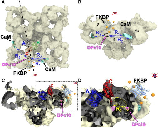
Location of HF647 attached to DPc10 bound to RyR2. (A) RyR1 viewed from the cytosolic side. The trilaterated position of the DPc10-attached acceptor is shown (magenta within black-dotted oval) relative to the cryo-EM structure of the closed RyR1 (EMDB:1606), the docked FKBP, the docked RyR ABC-domain, and the predicted locations of the CaM N- and C-lobes, as indicated (13). Distances between A-DPc10 and the N- and C-lobe of CaM on the same face of RyR are indicated by R1 and R2. R2′ indicates the distance between DPc10 and the C-lobe of CaM bound on adjacent faces of RyR. A vertical sectioning plane (dashed line) was used to create the cut-out views in C and D. (B) RyR1 is shown in side view. The trilaterated position of the DPc10-attached acceptor (dotted oval) was found in RyR domain 3 (the handle). A second solution generated by the same distances is on the opposite side of FKBP, well outside the cryo-EM map (red x). (C) Cut-out view perpendicular to the plane indicated in panel A. (Dark gray shading) Inside surfaces of the EM map revealed in cut-off. (D) Magnified view of the region (dashed box) in panel C. The distance of nearest approach between the C-domain (at residue 455) and the A-DPc10 locus (magenta) is R3 = 35 Å. A gallery that communicates with the cytosol (dotted yellow oval) allows DPc10 access to space around domain C, where it may perturb an interface (magenta shading) formed between the lower tip of the C-domain and a noncontiguous RyR domain. To see this figure in color, go online.