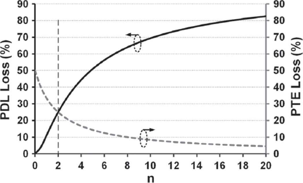
Fig. 2.
PTE and PDL losses in percentage with respect to their maximum possible values versus n when the two-coil link is designed to maximize the proposed FoM in (4) as opposed to the PTE or PDL. It can be seen that n = 2 results in similar PTE and PDL losses, equal to 25%. Similar curves can be derived for the three- and four-coil links.

