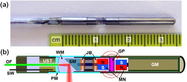
Fig. 26.
(a) Photo of the integrated mini–probe's rigid distal end. (b) Schematic of the mini–probe. GM, geared micromotor; GP, glass partition; JB, jewel bearings; MN, magnets; OF, optical fiber; PM, plastic membrane (imaging window); SM, scanning mirror; SW, signal wire; UST, ultrasonic transducer; WM, water medium [99].

