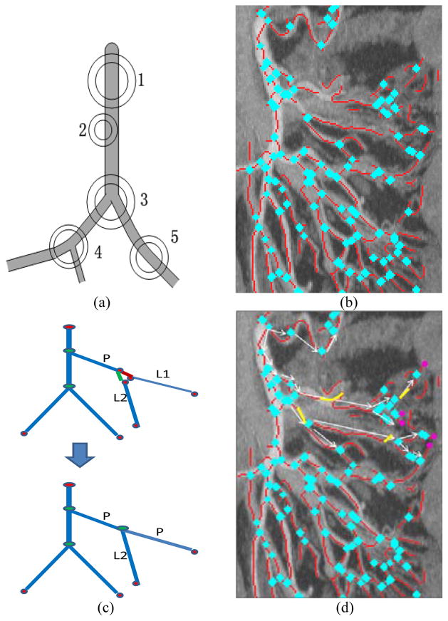
Fig. 10.
Building the mesenteric vessel tree. a) Schematic showing bifurcation (3, 4) and non-bifurcation (1, 2, 5) points. b) Bifurcation point detection results for the image shown in Figure 8 (blue points; only part of Fig. 8 is shown for better display), (c) illustration of reconnection procedure (d) Build the vessel map by filling gaps (yellow) and localizing the extremas of the mesenteric vessel tree (pink), only procedure of several branches and extremas are shown, which is used to show the idea not the result.

