. 2014 Sep 18;12(41):8132–8137. doi: 10.1039/c4ob01669f

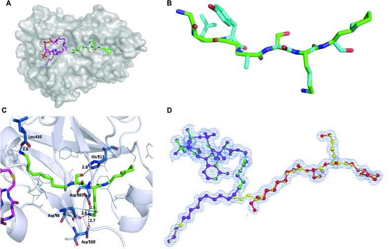
Fig. 2. (A) Co-crystal structure of PvNMT (chain C; grey surface) with bound NHM (magenta) and 10 (green), colored by atom. (B) Superimposition of peptide substrate (GLYASKL, blue) with 10 (green, 4c68) in PvNMT. The peptide was modeled to maximize overall structural similarity while maintaining peptide geometric restraints. (C) Ternary structure of 10 (green, sticks) and non-hydrolysable Myr-CoA (partially shown; magenta; sticks) in PvNMT (4c68) showing main recognition interactions between 10 and the enzyme. Residues within 4 Å of 10 are shown in blue. Polar interactions and their distances (in Å) are shown as dashed lines. (D) Refined electron density map showing the mixture of structures of 10 and myr-10 (yellow) in a ball and stick representation observed in LmNMT (4c7h). The figure shows the mixture of ligands present in the final refined model (80% reactants – purple and red and 20% products – green and yellow) shown in a ball-and-stick representation to aid identification. Electron density figures were made using the program CCP4 mg.22 See Fig. S2 (ESI) for more details.

Fig. 2