Abstract
This study reports on the correlation between crystal orientation and magnetic flux distribution of Fe3O4 nanoparticles in the form of self-assembled rings. High-resolution transmission electron microscopy demonstrated that the nanoparticles were single-crystalline, highly monodispersed, (25 nm average diameter), and showed no appreciable lattice imperfections such as twins or stacking faults. Electron holography studies of these superparamagnetic nanoparticle rings indicated significant fluctuations in the magnetic flux lines, consistent with variations in the magnetocrystalline anisotropy of the nanoparticles. The observations provide useful information for a deeper understanding of the micromagnetics of ultrasmall nanoparticles, where the magnetic dipolar interaction competes with the magnetic anisotropy.
Magnetic nanoparticles synthesized by chemical/colloidal methods1–3 have attracted considerable attention in the previous decade because of their potential for applications, such as drug delivery,3,4 contrast enhancement in magnetic resonance imaging,3,4 tracers for promising new magnetic particle imaging,5,6 and for the radio frequency method for cancer treatment (referred to as hypermedia).7–9 Among the candidate materials for these medical applications, magnetite (Fe3O4) has several advantages including excellent chemical stability, biocompatibility, and sufficiently large magnetic flux density (∼0.6 T), which enables efficient manipulation of the particles. From an engineering point of view, controlling the particle size and/or dispersion is crucial for optimizing functionalities such as heat generation7,10 or generation of contrast5,6 using magnetic nanoparticles in an alternating magnetic field.3 Another essential problem concerning the science and engineering of nanoparticles is revealing the magnetization distribution in specific self-organized arrangements. Microscopy observations could provide useful information for an understanding of spin textures that may be dependent on the complex morphology of nanoparticles.
With respect to the morphology of magnetic nanoparticles, transmission electron microscopy (TEM) observations have revealed basic forms of self-assembly, such as ring (or bracelet),11,12 chain,13–16 and other two-dimensional configurations.17,18 For the ring and chain forms, researchers have claimed a significant role of the magnetic dipolar interaction for achieving peculiar one-dimensional arrays of nanoparticles.1,11–13 It should be noted that many of the previous TEM studies were carried out using polycrystalline and/or multiply-twinned nanoparticles, in which the magnetocrystalline anisotropy (another essential factor for explaining the magnetic nanostructure) is weakened and/or averaged out. Thus, we need to investigate a different case, in which the magnetocrystalline anisotropy is pronounced and well-defined for individual nanoparticles. Such observations could shed further light on our understanding of micromagnetism of nanoparticles, where the magnetic dipolar interaction competes with the magnetocrystalline anisotropy. To examine this, we carried out electron holography studies using single-crystalline, monodispersed Fe3O4 particles with diameter of 25 nm.
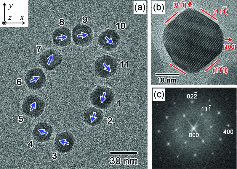
The Fe3O4 nanoparticles were synthesized by reacting predetermined amounts of Fe3+-oleate and oleic acid in 1-octadecene. The mixture was refluxed overnight (>24 h) at 593 K under argon with vigorous stirring. The final product was collected and washed four times with a 1:1 mixture of chloroform and methanol to remove excess surfactants and solvent. The as-synthesized particles were then coated with an amphiphilic polymer, poly(maleic anhydride-alt-1-octadecene) (PMAO), modified by covalent attachment of poly(ethylene glycol) (PEG, molecular weight 5000 kDa). After coating with PMAO-PEG, the particles were dispersed in water. See Ref. 19 for additional details on the synthesis of these nanoparticles. For TEM observations, the nanoparticles were placed on a copper grid coated with electron-transparent amorphous carbon by allowing a 10 μL drop of a particle-containing solution to evaporate in a drying oven at 473 K. A crystallographic structural analysis was carried out using a 300-kV electron microscope, a TITAN 80–300 (FEI). To reveal the magnetic flux distribution in the nanoparticles, electron holography studies were carried out using a 300-kV electron microscope, a HF-3300 S (Hitachi). The lateral resolution, defined to be three times the fringe spacing in electron holograms, was about 10 nm.20 Simulations of the magnetic flux map were carried out using the commercial computer code ELF/MAGIC (ELF Co.), which employs the integral element method. TEM observations ascertained three types of basic morphology of self-assembly for the Fe3O4 particles: chain, ring, and two-dimensional clusters.21 In this study, in order to reveal the relationship between the crystal orientations and magnetic flux lines, a ring-type assembly such as that shown in Fig. 1(a) was analyzed.
FIG. 1.
Morphology of ring-shaped self-assembly of Fe3O4 nanoparticles. (a) TEM image of Fe3O4 nanoparticles showing the ring-shaped self-assembly. (b) High-resolution TEM image of Fe3O4 nanoparticle. The particle was in an agglomeration different from the assembly shown in (a). (c) Digital diffractogram indicating the single-crystalline state of the nanoparticle shown in (b).
We first describe the crystallographic aspects of the nanoparticles. TEM observations showed that the synthesized Fe3O4 particles were monodispersed, and that the average particle size was 25 nm: i.e., for the ring shown in Fig. 1(a), the diameters (long axis) of the particles ranged from 22 to 28 nm. Figure 1(b) shows a high-resolution TEM image of a nanoparticle, which was observed in an agglomeration different from that shown in Fig. 1(a). The nanoparticle is in a single-crystalline state, showing no appreciable lattice imperfections such as twinning or stacking faults. Clear lattice fringes can be seen over the whole specimen region. The digital diffractogram in Fig. 1(c), which was obtained from the lattice image in Fig. 1(b), could be reasonably indexed assuming the inverse spinel-type structure of Fe3O4. These results indicate the excellent crystallinity of the synthesized nanoparticles. The nanoparticles showed major facets made of {111} planes, as indicated by the red lines in Fig. 1(b), in addition to minor facets such as {100}. Based on these observations, the Fe3O4 particles can be approximated by a truncated octahedral, as is discussed later in greater detail, although the actual particle shapes were not perfectly symmetric.
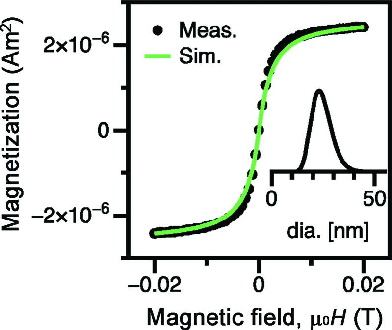
Fe3O4 nanoparticles with this diameter of ∼25 nm are near the critical transition size between superparamagnetism and ferrimagnetism.3,6 To reveal the magnetism of the synthesized nanoparticles, magnetization curves were acquired from water-dispersed nanoparticles at room temperature. As shown in Fig. 2, the magnetization curve (black dots) measured using a vibrating sample magnetometer (VSM) showed zero remanence and coercive field, indicating superparamagnetic behavior. The magnetization data could be reasonably well fitted using a Langevin function (green curve) assuming a log-normal size distribution,22 with a median particle diameter of 24 nm, which is not in contradiction to the electron microscopy observations. (The inset in Fig. 2 shows the probability distribution function for the particle diameter determined from the fitting process.) The saturation magnetization was assumed to be equal to the bulk value for magnetite, 446 kA/m, and the measurement temperature was 295 K. The geometric standard deviation was 1.2.
FIG. 2.
Hysteresis loop for water-dispersed specimen measured using a vibrating sample magnetometer. The observations (black dots) indicate that the nanoparticles are superparamagnetic under the measurement conditions used (room temperature, 1 s hold at each measured field). Data simulated for the fitted size using a Langevin function are also plotted (green curve).
The competing mechanisms that are responsible for the magnetism of nanoparticles should be mentioned. Some of the present authors observed that under alternating current excitation, the coercive field increased (relative to the VSM measurement) due to the short measurement time.23 This result indicates that nanoparticles of this size (∼25 nm) are near the critical transition between thermal energy dominance and anisotropy energy dominance. As the specimen was dried on the grid for the TEM observations, the relative contribution of the magnetostatic interaction appeared to increase, leading to ordering and self-assembly into a flux-closed loop. This is likely because the PEG layer collapsed as it dried, reducing the steric barrier between magnetic cores. We accordingly expect that electron holography can visualize a static magnetic flux distribution, which can be achieved by the ring-shaped self-assembly observed in the TEM specimens.
Electron holography was used to image the magnetic flux lines in the ring-shaped self-assembly. Here, we briefly touch upon the essence of electron holography. An electron wave that has traversed the specimen, referred to as the object wave, is subjected to a phase shift, ϕ, due to the electromagnetic field. With reference to the x-y-z coordinate shown in Fig. 1(a), in which the electron incidence is perpendicular to the x-y plane, ϕ can be expressed as
| (1) |
where, σ, V0, e, , and By represent the interaction constant, the electric potential, elementary charge, Planck's constant divided by 2π, and the y component of the magnetic flux density, respectively. The integral is carried out over the area enclosed by the paths of the electrons.24,25 Similarly, ϕ(y) can be related to the x component of the magnetic flux density.26 In the experiments, the object wave interferes with the reference wave (i.e., the electron wave free of phase modulation) to produce the electron hologram, which carries information about the phase shift. The phase information can be retrieved from the digitized electron hologram using a Fourier transform. This process yields a reconstructed phase image, such as that shown in Fig. 3(a). The result is presented in terms of cos ϕ(x,y), where contour lines trace positions with an equal phase shift magnitude. It should be noted that the phase shift shown in Fig. 3(a) has been amplified by a factor of 10.
FIG. 3.
Electron holography observations from nanoparticles shown in Fig. 1(a). (a) Original reconstructed phase image indicating a significant contribution from the mean inner potential, which is pronounced for nanoparticles. The phase information was amplified by a factor of 10. (b) Reconstructed phase image collected from the specimen, which was turned upside down with reference to the incident electrons. The phase information was amplified by a factor of 10. (c) Reconstructed phase image showing the magnetic information in this viewing field. The phase information was amplified by a factor of 100. The blue arrows and the red lines indicate the traces of the ⟨111⟩ axis and the outline of the nanoparticles, respectively. The result in (c) was subjected to noise filtering using a Fourier transform.
Although Fig. 3(a) shows concentric contour lines at the particle positions, this phase image is mostly due to the first term of Eq. (1), representing the contribution from the electric field. In particular, for Fe3O4 nanoparticles whose thickness in the incident electron direction varies strongly, the phase shift due to the mean inner potential is the most significant source of the phase shift. In order to separate the magnetic information [due to the second term of Eq. (1)] from the undesired electrical information, we obtained another reconstructed phase image after flipping the specimen so that it was upside down with reference to the incident electrons: see Fig. 3(b). For this observation, the sense of the phase shift was reversed for the magnetic field, although it remained unchanged for the electric field.27 A subtraction protocol using Figs. 3(a) and 3(b) erases the undesired contribution of the electric field, and accordingly reveals the magnetic field [Fig. 3(c)]. In the absence of the contribution from the electric field, the contour lines represent the lines of magnetic flux (in-plane component of magnetic flux) in the region of interest.24,25 The results of Fig. 3(c) were subjected to noise filtering, and the phase information was amplified by a factor of 100. The red lines and the blue arrows in the figure indicate the outline of individual nanoparticles and the trace of the plausible easy magnetization axis, respectively. The observation clearly shows the magnetic flux lines [i.e., contour lines in Fig. 3(c)] that trace the ring.
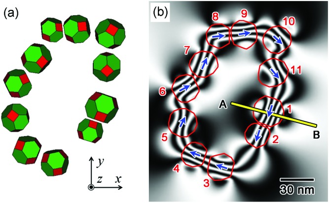
Magnetic flux lines tracing the rings have been observed for polycrystalline Co particles 11 and multiply-twinned Ni particles.12 In contrast to these previous observations, the contour lines in Fig. 3(c) are highly meandering, i.e., the direction of the magnetic flux lines changes significantly at several locations in the ring. To account for these fluctuations, we carried out simulations of the reconstructed phase image. As shown in Fig. 4(a), the nanoparticles were approximated by truncated octahedra, showing major facets of {111} planes (indicated in green) and minor facets of {100} planes (indicated in red). The size, location, and crystal orientation of the nanoparticles were fitted to the TEM observations.21 Assuming the magnetic flux density of the nanoparticles to be 0.6 T,28,29 we calculated the three-dimensional magnetic field, both inside and outside of the particles, using the commercial code ELF/MAGIC. When the three-dimensional magnetic field is known, calculation using the second term in Eq. (1) gives a reconstructed phase image such as that shown in Fig. 4(b).
FIG. 4.
Simulations of the magnetic flux distribution. (a) Structure model used in the simulation. The nanoparticles in Fig. 1(a) were approximated by truncated octahedra, for which the particle position, particle size, and crystal orientations were fitted to TEM observations. (b) Simulated reconstructed phase image showing the magnetic signals (representing magnetic flux lines) allowing for a comparison with Fig. 3(c). The blue arrows and red lines indicate the traces of the ⟨111⟩ axis and the outline of the nanoparticles, respectively. The simulated phase information was also amplified by a factor of 100.
The simulation reasonably explains the characteristic features of the observations. For the paired particles 1–2 and 3–4, the traces of the easy magnetization axis (blue arrows) are almost parallel. For these particle pairs, the magnetic flux lines are approximately parallel to the blue arrows in both the observations [Fig. 3(c)] and the simulation [Fig. 4(b)]. In contrast, the flux lines are deformed in a zig-zag manner for the particle arrays 5-6-7–8 and 10-11-1. In fact, at these locations, the blue arrows are neither mutually parallel, nor do they trace the ring. It can be concluded from these observations that the fluctuations in the contour lines can be attributed to the magnetocrystalline anisotropy, which is preserved in the ring-shaped self-assembly. We note that there was a small discrepancy in the shape of the flux lines (between the observations and simulation), for example, in particle 9. A plausible reason for this is the additional phase shift due to Bragg reflections. In principle, for the electron holography study, we chose those particles [viz, the observation in Fig. 1(a)] in which undesired diffraction contrast appeared to be suppressed. However, when the specimen was flipped upside down, in order to obtain the result shown in Fig. 3(b), we were unable to perfectly reproduce the same diffraction condition as that of Fig. 3(a): presumably, the deviation of the diffraction condition was significant for particle 9.
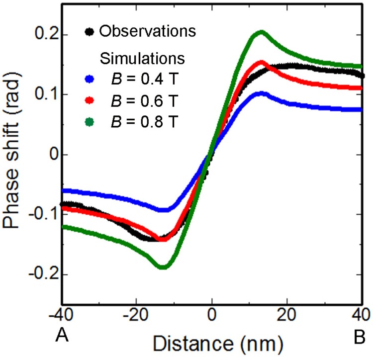
We attempted to determine the magnetic flux density for the synthesized Fe3O4 nanoparticles. For this purpose, the phase shift was measured along the yellow line A-B in Fig. 3(c) that crosses particle 1. The observations are plotted as black dots in Fig. 5. The other curves in Fig. 5 represent simulations, which, respectively, assume the magnetic flux density (B) in the particles to be 0.4 T (blue), 0.6 T (red), and 0.8 T (green). These plots suggest that the B value that best fits the observations is 0.6 T. Although a small deviation (∼0.03 rad, between the black and red curves) is observed in the side of B, this value is comparable with the uncertainty in the phase analysis (∼0.03 rad), which is deduced from the background noise. Assuming the magnetic flux density of the nanoparticles to be 0.6 T, this value corresponds to the flux density observed for bulk Fe3O4 crystals.28,29 Thus, within the accuracy of this electron holography study, we could not obtain any signatures indicating spin disorder in the neighborhood of the surface, which would suppress the effective magnetic flux density in the nanoparticles.
FIG. 5.
Comparison between observations (black) and simulations (blue, red, green) of the phase shift observed along the line A-B in Figs. 3(c) and 4(b). The simulations were carried out assuming the three values of magnetic flux density (B) of the Fe3O4 nanoparticles to be 0.4 T (blue), 0.6 T (red), and 0.8 T (green). The phase information is not amplified.
To summarize, our TEM observations demonstrated the excellent crystallinity of the monodispersed Fe3O4 nanoparticles (25 nm average size) synthesized using the colloidal method;8 the particles were single crystalline, showing neither twins nor stacking faults. The nanoparticles showed ring-shaped self-assembly as is widely observed in other magnetic metal nanoparticles. Electron holography revealed the magnetic flux map for the self-assembly, in which the flux lines were highly meandering at several portions in the ring. The fluctuations in the flux lines were reasonably explained by the magnetocrystalline anisotropy that was preserved in the nanoparticles forming the ring-shaped assembly. The magnetic flux density for the nanoparticles was determined to be 0.6 T, which was consistent with the value for bulk Fe3O4 crystals, and no evidence of significant surface spin disorder was observed.
Acknowledgments
The authors are grateful to Dr. T. Matsuda, Mr. S. Aizawa, and Mr. Y. Hayasaka for their collaboration and useful discussions. This research was supported by a grant from the Japan Society for the Promotion of Science (JSPS) through the “Funding Program for World-Leading Innovative R&D on Science and Technology (FIRST Program)” initiated by the Council for Science and Technology Policy (CSTP), and a Grant-in-Aid for Scientific Research from JSPS. Work at UW was supported by NIH Grant Nos. 1R01EB013689-01/NIBIB and 1R41EB013520-01.
References
- 1.Puntes V. F., Krishnan K. M., and Alivisatos A. P., Science 291, 2115 (2001). 10.1126/science.1057553 [DOI] [PubMed] [Google Scholar]
- 2.Pankhurst Q. A., Connolly J., Jones S. K., and Dobson J., J. Phys. D: Appl. Phys. 36, R167 (2003). 10.1088/0022-3727/36/13/201 [DOI] [Google Scholar]
- 3.Krishnan K. M., IEEE Trans. Magn. 46, 2523 (2010). 10.1109/TMAG.2010.2046907 [DOI] [PMC free article] [PubMed] [Google Scholar]
- 4.Sun C., Lee J. S. H., and Zhang M., Adv. Drug Delivery Rev. 60, 1252 (2008). 10.1016/j.addr.2008.03.018 [DOI] [PMC free article] [PubMed] [Google Scholar]
- 5.Gleich B. and Weizenecker J., Nature 435, 1214 (2005). 10.1038/nature03808 [DOI] [PubMed] [Google Scholar]
- 6.Ferguson R. M., Khandhar A. P., Arami H., Hua L., Hovorka O., and Krishnan K. M., Biomed. Tech. (Berl) 58, 493 (2013). 10.1515/bmt-2012-0058 [DOI] [PMC free article] [PubMed] [Google Scholar]
- 7.Gonzales-Weimuller M., Zeisberger M., and Krishnan K. M., J. Magn. Magn. Mater. 321, 1947 (2009). 10.1016/j.jmmm.2008.12.017 [DOI] [PMC free article] [PubMed] [Google Scholar]
- 8.Khandhar A. P., Ferguson R. M., and Krishnan K. M., J. Appl. Phys. 109, 07B310 (2011). 10.1063/1.3556948 [DOI] [PMC free article] [PubMed] [Google Scholar]
- 9.Mamiya H. and Jeyadevan B., Sci. Rep. 1, 157 (2011). 10.1038/srep00157 [DOI] [PMC free article] [PubMed] [Google Scholar]
- 10.Rosensweig R. E., J. Magn. Magn. Mater. 252, 370 (2002). 10.1016/S0304-8853(02)00706-0 [DOI] [Google Scholar]
- 11.Tripp S. L., Dunin-Borkowski R. E., and Wei A., Angew. Chem. Int. Ed. 115, 5749 (2003). 10.1002/ange.200352825 [DOI] [PubMed] [Google Scholar]
- 12.Sugawara A., Fukunaga K., Scheinfein M. R., Kobayashi H., Kitagawa H., and Tonomura A., Appl. Phys. Lett. 91, 262513 (2007). 10.1063/1.2827586 [DOI] [Google Scholar]
- 13.Dunin-Borkowski R. E., McCartney M. R., Frankel R. B., Bazylinski D. A., Pósfai M., and Buseck P., Science 282, 1868 (1998). 10.1126/science.282.5395.1868 [DOI] [PubMed] [Google Scholar]
- 14.Hÿtch M. J., Dunin-Borkowski R. E., Scheinfein M. R., Moulin J., Duhamel C., Mazaleyrat F., and Champion Y., Phys. Rev. Lett. 91, 257207 (2003). 10.1103/PhysRevLett.91.257207 [DOI] [PubMed] [Google Scholar]
- 15.Signoretti S., Bianco L. Del, Pasquini L., Matteucci G., Beeli C., and Bonetti E., J. Magn. Magn. Mater. 262, 142 (2003). 10.1016/S0304-8853(03)00037-4 [DOI] [Google Scholar]
- 16.Gao Y., Shindo D., Bao Y., and Krishnan K., Appl. Phys. Lett. 90, 233105 (2007). 10.1063/1.2747052 [DOI] [Google Scholar]
- 17.Varón M., Beleggia M., Kasama T., Harrison R. J., Dunin-Borkowski R. E., Puntes V. F., and Frandsen C., Sci. Rep. 3, 1234 (2013). 10.1038/srep01234 [DOI] [PMC free article] [PubMed] [Google Scholar]
- 18.Yamamuro S., Yamamoto K., Peng D. L., Hirayama T., and Sumiyama K., Appl. Phys. Lett. 90, 242510 (2007). 10.1063/1.2748077 [DOI] [Google Scholar]
- 19.Khandhar A. P., Ferguson R. M., Simon J. A., and Krishnan K. M., J. Biomed. Mater. Res. Part A 100A, 728 (2012). 10.1002/jbm.a.34011 [DOI] [PMC free article] [PubMed] [Google Scholar]
- 20.Völkl E., Allard L. F., and Joy D. C., Introduction to Electron Holography ( Kluwer Academic/Plenum Publishers, New York, 1999). [Google Scholar]
- 21.See supplementary material at http://dx.doi.org/10.1063/1.4901008E-APPLAB-105-070444 for the basic morphologies and the crystal orientations of the nanoparticles.
- 22.Chantrell R. W., Popplewell J., and Charles S. W., IEEE Trans. Magn. 14, 975 (1978). 10.1109/TMAG.1978.1059918 [DOI] [Google Scholar]
- 23.Tomitaka A. T., Ferguson R. M., Khandhar A. P., Kemp S. J., Ota S., Nakamura K., Takemura Y., and Krishnan K. M., “Variation of magnetic particle imaging tracer performance with amplitude and frequency of the applied magnetic field,” IEEE Trans. Magn. (in press). [DOI] [PMC free article] [PubMed] [Google Scholar]
- 24.Tonomura A., Electron Holography, 2nd ed. ( Springer-Verlag, Berlin, 1999). [Google Scholar]
- 25.Shindo D. and Murakami Y., J. Phys. D: Appl. Phys. 41, 183002 (2008). 10.1088/0022-3727/41/18/183002 [DOI] [Google Scholar]
- 26.Murakami Y., Niitsu K., Tanigaki T., Kainuma R., Park H. S., and Shindo D., Nat. Commun. 5, 4133 (2014). 10.1038/ncomms5133 [DOI] [PMC free article] [PubMed] [Google Scholar]
- 27.Tonomura A., Osakabe N., Matsuda T., Kawasaki T., Endo J., Yano S., and Yamada H., Phys. Rev. Lett. 56, 792 (1986). 10.1103/PhysRevLett.56.792 [DOI] [PubMed] [Google Scholar]
- 28.Kasama T., Harrison R. J., Church N. S., Nagao M., Feinberg J. M., and Dunin-Borkowski R. E., Phase Trans. 86, 67 (2013). 10.1080/01411594.2012.695373 [DOI] [Google Scholar]
- 29.Chang M. T., Chou L. J., Hsieh C. H., Chueh Y. L., Wang Z. L., Murakami Y., and Shindo D., Adv. Mater. 19, 2290 (2007). 10.1002/adma.200602330 [DOI] [Google Scholar]
Associated Data
This section collects any data citations, data availability statements, or supplementary materials included in this article.
Data Citations
- See supplementary material at http://dx.doi.org/10.1063/1.4901008E-APPLAB-105-070444 for the basic morphologies and the crystal orientations of the nanoparticles.


