Fig. 4.
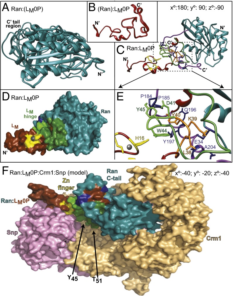
Solution structure of Ran:LM0P. (A) Ten low-energy states for Ran:(LM0P). (B) Ten low-energy states for (RAN):LM0P. All coordinates are as deposited with PDB. (C) HADDOCK-determined state-1 of Ran:(LM0P) docked to state-1 (Ran):LM0P. C’ tail region of Ran, wrapping around LM0P is highlighted (purple). Ran rotation relative to A is indicated. Stereo version of this image is in Fig. S6. (D) Similar to C, Ran (blue), LM0P (brown), zinc coordination residues (yellow), and hinge region contacts (green) are highlighted. (E) Similar to C and D, close-up shows orientations of key Ran:LM0P interaction regions. (F) State-1 Ran:(LM0P) coordinates were aligned and then substituted into PDB ID code 3GJX, a crystallographically determined complex of Ran (blue), Crm1 (tan), and snurportin1 (pink). Relative to D, the required rotation for Ran:LM0P is indicated. The loop of Ran (blue) encircling LM0P (brown, yellow, green) is the C′ tail. The LM phosphorylation sites are buried in the Crm1 (T51) and Snp (Y45) interfaces.

