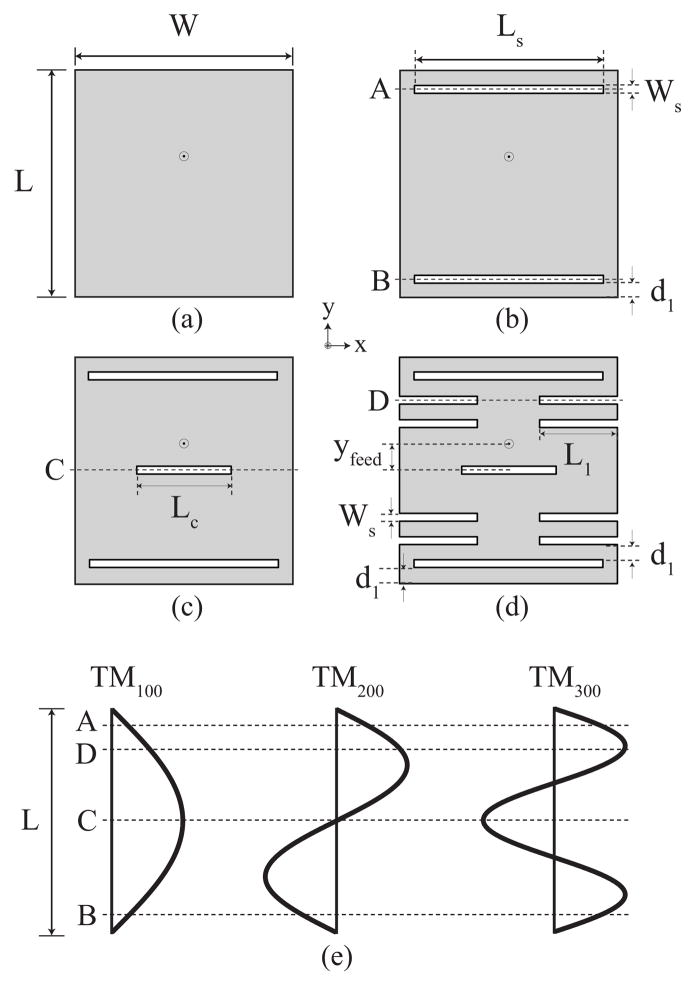
Fig. 2.
Top view of the (a) basic patch, (b) patch loaded with radiating-edge slots (RS), (c) patch loaded with radiating-edge and center slots (RS+CS), and (d) patch loaded with radiating-edge, center, and non-radiating edge slots (RS+CS+NRS). (e) Schematic of current distributions for the first three longitudinal modes showing where the current is affected by the various slots in (b)–(d).

