Figure 4.

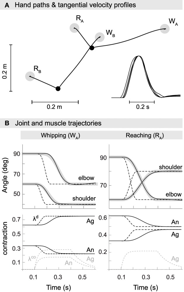
Kinematics of model reaching and whipping movements. (A) Hand paths in extrinsic space. Gray disks indicate target positions for reaching (RA,B) and whipping movements (WA,B). Black points indicate initial positions. Trajectories are approximately straight with small hooks at the target positions. Inset at the bottom right are normalized tangential velocity profiles scaled by maximum velocity and shifted such that peaks coincide. The profiles are approximately bell-shaped with some overshoot. (B) Trajectories in joint space (first row). In black are shown actual and in gray desired joint trajectories. Also plotted as dashed lines are the commanded joint trajectories, i.e., the virtual equilibrium joint angles corresponding to the central commands λd. Second row: muscle trajectories for both agonist and antagonist of the shoulder. Muscle excursion is here measured as a proportion of maximum contraction, i.e., a value of 1 corresponds to a muscle being maximally contracted (at its shortest) and a value of 0 to it being minimally contracted (at its longest). Shown are the commanded muscle threshold λd (black, dashed), actual muscle contraction (black) and the open-loop component λco (gray, dashed).
