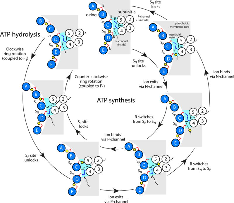
Figure 6.

Proposed microscopic mechanism of c-ring rotation coupled to ion transport. The diagram shows the interface between the c-ring, represented by five of the outer helices (blue circles), and subunit-a, in the topology of TM2-TM5 (white circles) predicted by cross-linking data64. Two aqueous half-channels mediate ion exchange across the a/c complex with either the P-side (outside) or the N-side (inside) of the energized membrane (black dashed lines). Hydration of the c-ring binding sites (SP and SN, respectively) facilitates loading and release of ions (yellow spheres) via isomerization of a conserved glutamate/aspartate (E, red sticks). A conserved arginine in subunit-a (R, blue sticks) forms alternating salt-bridges with SP and SN and thus prevents the ion from hopping between these sites, i.e. it effectively provides an electrostatic barrier between the P and N-channels. The directionality of the mechanism is thus imposed by the clockwise arrangement of SP and SN sites: downhill ion permeation (i.e. from P to N) necessarily implies counter-clockwise c-ring rotations (powering ATP synthesis), while clockwise rotations (driven by ATP hydrolysis) imply uphill transport (i.e. from N to P).
