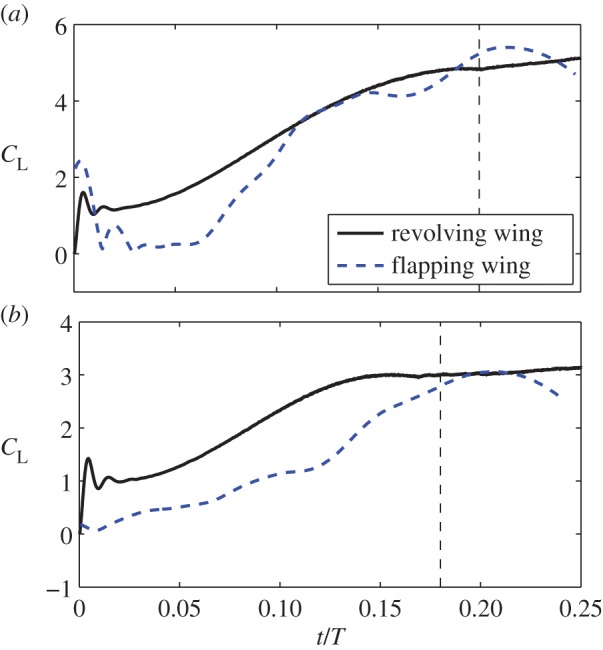
Figure 9.

The revolving wing versus the flapping wing in the production of lift. (a) Downstroke and (b) upstroke. Only one typical stroke cycle is used in this test. The vertical dashed line represents the time period of wing acceleration. All forces are normalized by the same factor. (Online version in colour.)
