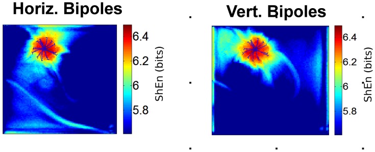
Figure 4. Effect of Bipole Orientation.
The effect of bipole EGM orientation is shown. The left panel shows a ShEn map for the CRN model rotor with bipoles in the horizontal orientation (bipole distance = 2 mesh elements). ShEn maps are shown with the trajectory of the spiral wave tip annotated in blue. The right panel shows a ShEn map with bipoles in the vertical orientation.

