Abstract
Purpose:
The use of medical technology capable of tracking patient motion or positioning patients along 6 degree-of-freedom (6DOF) has steadily increased in the field of radiation therapy. However, due to the complex nature of tracking and performing 6DOF motion, it is critical that such technology is properly verified to be operating within specifications in order to ensure patient safety. In this study, a robotic motion phantom is presented that can be programmed to perform highly accurate motion along any X (left–right), Y (superior–inferior), Z (anterior–posterior), pitch (around X), roll (around Y), and yaw (around Z) axes. In addition, highly synchronized motion along all axes can be performed in order to simulate the dynamic motion of a tumor in 6D. The accuracy and reproducibility of this 6D motion were characterized.
Methods:
An in-house designed and built 6D robotic motion phantom was constructed following the Stewart–Gough parallel kinematics platform archetype. The device was controlled using an inverse kinematics formulation, and precise movements in all 6 degrees-of-freedom (X, Y, Z, pitch, roll, and yaw) were performed, both simultaneously and separately for each degree-of-freedom. Additionally, previously recorded 6D cranial and prostate motions were effectively executed. The robotic phantom movements were verified using a 15 fps 6D infrared marker tracking system and the measured trajectories were compared quantitatively to the intended input trajectories. The workspace, maximum 6D velocity, backlash, and weight load capabilities of the system were also established.
Results:
Evaluation of the 6D platform demonstrated translational root mean square error (RMSE) values of 0.14, 0.22, and 0.08 mm over 20 mm in X and Y and 10 mm in Z, respectively, and rotational RMSE values of 0.16°, 0.06°, and 0.08° over 10° of pitch, roll, and yaw, respectively. The robotic stage also effectively performed controlled 6D motions, as well as reproduced cranial trajectories over 15 min, with a maximal RMSE of 0.04 mm translationally and 0.04° rotationally, and a prostate trajectory over 2 min, with a maximal RMSE of 0.06 mm translationally and 0.04° rotationally.
Conclusions:
This 6D robotic phantom has proven to be accurate under clinical standards and capable of reproducing tumor motion in 6D. Such functionality makes the robotic phantom usable for either quality assurance or research purposes.
Keywords: quality assurance, robotic, 6DOF, motion phantom, rotational organ motion
1. INTRODUCTION
A clinical target volume (CTV) is capable of undergoing both translational and rotational motions. Although the deleterious effects of poor translational localization of the CTV are well known, recent studies have shown that tumor rotational localization error can also significantly affect the target dose coverage.1–8 This is particularly concerning in the case of highly conformal radiation therapy such as stereotactic radiosurgery (SRS) and intensity-modulated radiation therapy (IMRT). In these cases, even tumors which are well-positioned in the X (left–right, LR), Y (superior–inferior, SI), and Z (anterior–posterior, AP) axes can still produce significant sources of uncertainty with regard to efficacy of the intended dose distribution in the patient, especially if they are significantly nonspherical.8,9
The ability to track and correct for target motion in 6 degrees-of-freedom (6DOFs) has become more achievable with the introduction of new motion monitoring techniques and patient positioning devices. External 6DOF patient tracking has been performed using either infrared (IR) marker tracking or 3D optical surface imaging.10–14 Internal 6DOF tracking of targets within the patient has been performed using stereoscopic kV imaging, using single planar kV images to estimate 6D motion in real-time or magnetic fiducial tracking.9,15–20 Devices capable of positioning patients in 6DOF include robotic treatment couches such as the Elekta HexaPOD system (Elekta, Stockholm, Sweden) and the Varian TrueBeam 6D couch (Varian, Inc., Palo Alto, CA).21–23
Despite the growth of 6D-capable motion tracking and patient positioning technologies in the clinic, there does not currently exists a versatile 6DOF radiation therapy-specific motion phantom to verify that such devices are operating within designed specifications. Previous work which characterized such 6DOF technology had been limited to performing well-defined reference motions along only the translation axes XYZ or along XYZ and the yaw axes.24 While other research groups have explored task-specific 6DOF phantoms, a compact and versatile phantom with a height weight load for integration with other anthropomorphic phantoms does not currently exist with adequate performance characteristics to permit replication of tumor motion at multiple sites.25 In addition, a trend in recent research to consider 6DOF in motion tracking, artifact generation during imaging, and dosimetric effects promotes the necessity for a highly accurate device capable of performing specific trajectories to verify proposed methodologies for the reduction of motion-induced deleterious effects.9,14,26–29 In this study, we present a robotic motion phantom that can be programmed to perform highly accurate motion along any X, Y, Z, pitch, roll, and yaw axes. Moreover, highly synchronized motion along all axes can be performed in order to simulate the real-time motion of a target in 6D, and in this work, we focus on the 6D motion of both cranial and prostate cases.
2. METHODS AND MATERIALS
2.A. Theory
Compared to a stacked serial kinematics 6D system, the Stewart–Gough archetype has several significant advantages, including improved compactness, a higher load-to-weight ratio, increased longevity, higher stiffness, and a faster response time.30,31 We consequently chose to follow the Stewart platform technique for a more robust 6D device. The two fundamental approaches to control a Stewart platform parallel kinematics stage are inverse kinematics and forward kinematics; since our application involves the generation of six leg trajectories to perform a desired 6D composite motion, we were motivated to use the former technique. This approach takes the desired X, Y, Z, pitch, roll, and yaw positions of the top platform and computes the required leg lengths for this position, over a 6D trajectory.
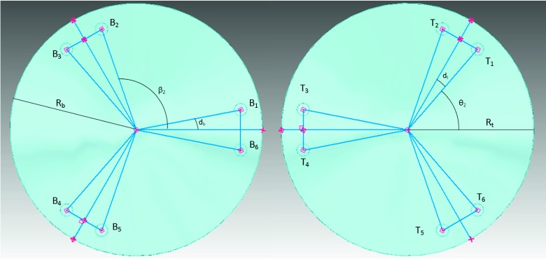
The six actuator legs of the Stewart platform connect to two universal joints each, one on the top platform at points Ti for i = 1, …, 6 and one on the bottom platform at points Bi for i = 1, …, 6. In the top platform frame and the bottom platform frame, these positions are given by Eqs. (1) and (2), respectively, for legs k = 1, …, 6, where the angles θk and βk are the angular positions of the universal joints on the top and bottom platforms, respectively, and RT and RB are the corresponding radii of the two platforms (see Fig. 1),
| (1) |
| (2) |
FIG. 1.
Geometry of the bottom (left) and top (right) platforms. The points Bi and Tj for i, j = 1, …, 6 correspond to the joint locations on the bottom and top platforms, respectively, where each actuator leg connects Bi and Tj when i = j. The angles db and dt correspond to the separation of the universal joint positions between the two most adjacent joints, for the bottom and top platforms, respectively.
Using this geometrical formulation, one can compute the required strut lengths sk to produce the intended top platform 6D position and orientation relative to the bottom platform R from the top and bottom universal joint positions in their frame, and , respectively, by Eq. (3),
| (3) |
2.B. Design and construction
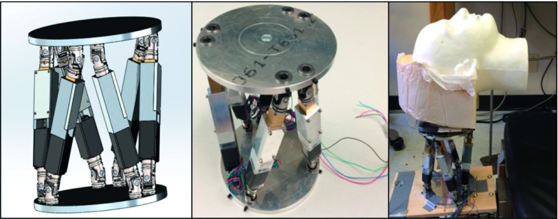
Following the geometrical consideration described above, the robotic stage was designed under the constraints of high compactness, weight load, and precision. Specifically, we developed the robotic motion phantom to be sufficiently compact so as to maximize its utility in multiple applications, selecting a platform radius of 75 mm and a stationary height of 183 mm. Due to the lack of commercially available actuators which matched the required sub-millimeter precision specifications, custom linear actuators, together with the top and bottom platforms of the parallel kinematics device, were designed and built in-house (Fig. 2). Each actuator was powered by a NEMA 8 stepper motor (OSM Technology) and controlled using an 8-axis stepper motor controller [PCI-7358 National Instruments (NI)].
FIG. 2.
Design of the 6D robotic phantom in SolidWorks (Dassault Systèmes SolidWorks Corp., Vélizy, France) (left), the completed device (middle), and the lab setup (right).
The lead screw-motor system was selected to provide substantial vertical lift capabilities such that the device was capable of performing 6DOF motions with common anthropomorphic phantoms, such as a water-equivalent head phantom; theoretical expectations yield a proposed weight load capacity of 32 kg at a motor speed of 45 rotations/s following Eq. (4), where dm is the lead screw diameter (6 mm), l is the thread [0.64 mm, corresponding to a high-resolution 40 threads/inch (0.64 threads/mm)], and μ is the coefficient of friction between the Kerkote TFE-coated lead screw and the Delrin antirotation collar (0.08 static, 0.09 dynamic),
| (4) |
Under the formulation, the robotic stage has the capacity to support a multitude of clinically used phantoms in order to provide controlled 6D motions to currently used phantoms. Additionally, the fine thread on the lead screw was selected to provide an exceptional accuracy of 3149 steps/mm, after tuning the stepper motor software to produce a control at the level of 2000 steps/rotation.
2.C. Evaluation
The accuracy and reproducibility of the robotic motion stage was characterized through comparison of measurements of its 6DOF output trajectory to different intended 6DOF input trajectories. The input files included repeated motions along each single axis to verify reproducibility and test the full 6D workspace, as well as more complicated trajectories to determine the full range of 6D capabilities of the device. Human 6D motion included prior recorded volunteer head motion over a 15 min period and patient prostate motion over a 2 min period.9,26 These input trajectories were then transmitted to a LabVIEW (2012, National Instruments) application and subsequently communicated to the six motors through the NI PCI-7358 controller card and the two stepper motor power drives.
Output motion of the robotic stage was tracked using an IR optical tracking camera (Polaris, Northern Digital, Inc., Waterloo, ON, Canada). Here, a 4-point reflective marker tool was fixed to the top platform of the device whose motion was monitored in real-time. The four markers on the tool define a set of vectors directed to a point in space, established at the control point of the Stewart platform, such that the resultant 6D motion of the device could be effectively compared to the intended trajectory. To ensure proper alignment of the device coordinate system, a transformation was performed between the Polaris coordinate frame and the IR tool frame, which was previously established as the Stewart platform frame of Ref. 32. To perform this transformation, an 8-point calibration technique was performed, wherein the robotic device moved across a 3D trajectory to the corners of a cube and remained stationary for 90 s (∼1000 data points at a Polaris frame rate of 12 Hz) to provide good statistics for averaging. The translational component of the Polaris output was averaged over the 90 s duration of all eight points of the cube corners and compared to the input X, Y, and Z positions using singular value decomposition (SVD).33 This methodology considers the two reference frames xn and yn with weight wn between each pair, for n = 1, 2, …, 8 positions and attempts to find an orthogonal matrix U = uij which minimizes Eq. (5) below, subject to the constraint in Eq. (6), where δij are the elements of the unit matrix,
| (5) |
| (6) |
The elements of this orthogonal matrix U are found by Eq. (9) below, with the unit eigenvectors of , ak and bk defined by Eq. (7), and the elements of matrix R, rij, defined by Eq. (8) below. Here, μk are the associated positive eigenvalues of ,
| (7) |
| (8) |
| (9) |
This technique permits accurate tracking of the robotic stage in 6D, and excluding the inherent Polaris noise and minimal setup uncertainty is an error minimizing procedure. A comprehensive analysis was performed to ascertain the 6D top platform position errors produced from the individual sources of uncertainty. Upon completing the calibration, several trajectories were transmitted to the stage and recorded using Polaris, and the root mean square error (RMSE) was computed over the entire duration of each motion to validate the efficacy of the 6D system.
The 6D workspace was then tested to determine the full range of motion capable; these values were computed for movements performed only in the direction reported since specific 6D orientations of the top platform can yield a myriad of restrictions on the workspace for that particular configuration (Table I). The relative directions selected for X, Y, and Z are arbitrary, but consistent following the geometry established in the design of the robotic stage. The maximum velocities in each six directions were also theoretically calculated given the limits of the stepper motors and a computed actuator maximum speed of 31.75 mm/s. Experimentally, the actuators were found to be capable of linear speeds of up to 20.32 mm/s, yielding the maximum 1D speeds in all six possible directions.
TABLE I.
Summary of maximum workspace and maximum speed of the 6D robotic phantom in all six dimensions. Values correspond to 1D motions in the recorded direction.
| X | Y | Z | Pitch | Roll | Yaw | |
|---|---|---|---|---|---|---|
| Minimum position | −42.2 mm | −51.5 mm | −15.6 mm | −14.7° | −15.0° | −41.0° |
| Maximum position | 42.2 mm | 39.4 mm | 15.5 mm | 14.3° | 15.0° | 41.0° |
| Maximum speed (theoretical) | 55.8 mm/s | 53.8 mm/s | 29.3 mm/s | 27.1 deg/s | 28.4 deg/s | 69.7 deg/s |
| Maximum speed (experimental) | 40.7 mm/s | 38.1 mm/s | 18.8 mm/s | 17.4 deg/s | 18.1 deg/s | 44.6 deg/s |
Having substantiated the theoretical capabilities of the robotic QA phantom with experiment, the 6D capabilities of the device were then examined. Six 1D trajectories were first performed to validate the reproducibility and effectiveness of the stage in all six dimensions independently. The measured output trajectory was then compared to the intended input trajectory, after the calibration procedure was performed. The full 6D capabilities of the system were then explored using previously acquired cranial motion and tracked using the Polaris IR tracking system as before. A similar procedure was conducted for 6D prostate motion, acquired previously using an iterative closest point algorithm and a kV imaging system.9 For both of these sites, the input trajectory was compared to the output trajectory as measured with the IR motion tracking system, using an RMSE analysis. For all cases of 6DOF motion, each trajectory and subsequent RMSE comparison were performed multiple times to further verify the reproducibility of the device.
3. RESULTS
3.A. Experimental setup characteristics
The uncertainty in the 6D positional accuracy of the device was analyzed assuming conservative estimates of the initial actuator lengths and the center of the universal joint pivot points, which define the control point of the top platform.34 Under the assumption of normally distributed initial 6D setup errors of the robotic stage in the above elements, with standard deviations of 0.1 mm translationally in both the initial actuator length and universal joint pivot positions, we found the mean of the translational errors to be zero with RMSE of 0.01, 0.02, and 0.01 mm in X, Y, and Z, respectively, and the mean of the rotational errors to be zero with RMSE of 0.01° in all pitch, roll, and yaw. These values were obtained after 10 000 simulated points sampled in a workspace ±2 mm in X, Y, and Z and ±1° in pitch, roll, and yaw; this workspace covers the 6D span of both the cranial and prostate motions. For larger workspaces such as ±15 mm and ±15° translationally and rotationally, respectively, if random points within this full 6D workspace were sampled as before and included the same normally distributed estimates of setup error, the RMSE of the robotic stage from this uncertainty alone was found to be at most 0.15 mm translationally and 0.08° rotationally.
3.B. Motion control in 6D
The results of the six independent 1D motion analyses are shown in Fig. 3 for translational and rotational motions. We obtained RMSE values of 0.14, 0.22, 0.08 mm, 0.16°, 0.06°, and 0.08° for X, Y, Z, pitch, roll, and yaw, respectively. As displayed in the figures, the 6D system exhibited excellent levels of reproducibility with minimal backlash over a substantial range of motion. As can be seen in the lower plot components in Fig. 3, which characterize the difference between the intended trajectory and the measured output trajectory, the error does not vary substantially over time nor does it increase significantly at the transition point in the trajectory between linear 1D motion and rest, indicating low backlash levels and a high degree of reproducibility.
FIG. 3.
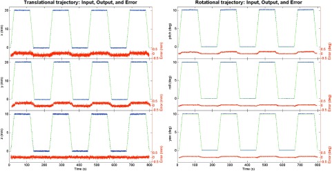
Comparison between input (ideal, no noise) and output (recorded, with noise) translational motions for 20 mm in X (top left) and Y (center left) and 10 mm in Z (bottom left), with resultant RMSE values of 0.14, 0.22, and 0.08 mm, respectively. Rotationally, a comparison was made for 10° in pitch around X (top right), roll around Y (center right), and yaw around Z (bottom right), with resultant RMSE values of 0.16°, 0.06°, and 0.08°, respectively. Below the comparison plot is the difference between the intended input trajectory and the measured output trajectory.
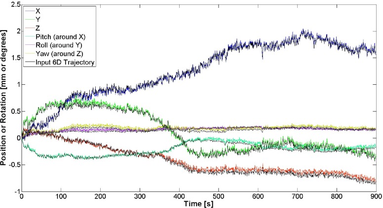
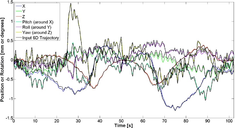
The recorded output motion in the cranial case was compared to the intended 6D trajectory, and over a 15 min trajectory, we found RMSE values of 0.03, 0.04, 0.04 mm, 0.03°, 0.02°, and 0.04° in X, Y, Z, pitch, roll, and yaw, respectively (Fig. 4). For the 6D prostate motion, the IR-recorded output motion was once again compared to the desired trajectory over a 110-s trajectory, and we found RMSE values of 0.03, 0.06, 0.02 mm, 0.03°, 0.04°, and 0.04° in X, Y, Z, pitch, roll, and yaw, respectively (Fig. 5). For both the cranial and prostate cases, the difference between the intended trajectory and the measured trajectory, even over a 15-min trajectory, does not vary substantially over time, and furthermore that this difference is within an envelope of ±0.15 mm and ±0.16° for both cases over the entire trajectories.
FIG. 4.
Comparison between input and output 6D head motions for X, Y, Z, pitch, roll, and yaw, with resultant RMSE values of 0.03, 0.04, 0.04 mm, 0.03°, 0.02°, and 0.04°, respectively.
FIG. 5.
Comparison between input and output 6D prostate motions for X, Y, Z, pitch, roll, and yaw, with resultant RMSE values of 0.03, 0.06, 0.01 mm, 0.03°, 0.04°, and 0.04°, respectively.
4. DISCUSSION
The presented 6D robotic system has demonstrated a high level of accuracy in replicating input 6D trajectories, while maintaining many of the robust and important features of a parallel kinematics machine, such as high load-to-weight ratio, compactness, longevity, speed, and reproducibility. Furthermore, validation of theoretical characteristics of the device was conducted experimentally, and a large 6D workspace was established. The device was also shown to have notable speed capabilities, with maximum translational and rotational speeds of up to 4 cm/s and 44 deg/s, further supporting its multipurpose functionality. As presented in the RMSE results and in Figs. 3–5, the robotic system is capable of rapid direction changes; the inherent noise in the Polaris tracking system increased the variability from set point to set point, demanding swift alteration of direction and sharp increases in instantaneous velocity. The response time and communication lag between the software and various hardware components were found to be sufficiently small, providing effective motion control even over irregular trajectories, such as those for tumors. Although such lesions are also capable of undergoing deformations, this work focused on the replication of rigid 6D motion, as deformable motion trajectories are substantially more complex and would require site-specific phantoms.
The development of a novel approach to calibrating the phantom to the IR camera system using an eight-point trajectory was effective and essential to providing valid 6D motion tracking at the sub 0.5-mm level. The eight points used for this calibration step are not uniquely necessary, since the SVD approach to yield a rotation matrix and translation vector relating the IR camera frame of reference to the 6D phantom top platform requires only six linearly independent points to provide enough equations for the unknown variables. However, increasing the number of points, in addition to extending the “wait time” at each point, helped reduce the inherent IR camera tracking error. Furthermore, previous studies have examined the standard deviation of the IR camera noise to be on the order of 0.07 mm translationally.26 Additional sources of uncertainty during calibration included the initial length of each actuator leg and the uncertainty in the absolute positions of the 12 universal joint pivot points which define the control coordinate system. These uncertainties contributed less than 0.2 mm and 0.1° from RMSE analysis translationally and rotationally, respectively, assuming conservatively large initial uncertainties and a workspace of ±15 mm in XYZ and ±15° in pitch, roll, and yaw. Ultimately, the acquisition of an ample set of data points at each resting point, used in conjunction with the robust and error free method of SVD, produced an effective methodology for tracking 6D motion in an arbitrary coordinate system while mitigating the innate uncertainty involved in IR tracking.
5. CONCLUSION
A versatile, accurate, and effective 6DOF robotic motion phantom for use in radiation therapy QA and for research purposes has been designed and fabricated under stringent requirements for workspace, speed, precision in replicating complex 6D motions, and ability to respond to rapid changes in direction. In combination with the high degree of accuracy achievable by the device and its compact size, the robotic 6D motion system presented here has a high degree of flexibility and can support a wide range of applications for simulating the motion of several tumor locations and anatomical features.
ACKNOWLEDGMENTS
This work was funded in part by the National Institutes of Health T32-EB002103 Training Grant from the National Institute of Biomedical Imaging and Bioengineering and by American Cancer Society Grant No. RSG-13-313-01-CCE. The authors would also like to thank Dr. Paul Keall and Dr. Joubin Tehrani for their contributions of 6D prostate motion files using their iterative closest point algorithm with kV imaging.
REFERENCES
- 1.Jiang S. B.et al. , “An experimental investigation on intra-fractional organ motion effects in lung IMRT treatments,” Phys. Med. Biol. 48, 1773–1784 (2003). 10.1088/0031-9155/48/12/307 [DOI] [PubMed] [Google Scholar]
- 2.Bortfeld T., Jiang S. B., and Rietzel E., “Effects of motion on the total dose distribution,” Semin. Radiat. Oncol. 14, 41–51 (2004). 10.1053/j.semradonc.2003.10.011 [DOI] [PubMed] [Google Scholar]
- 3.Stroom J. C., de Boer H. C., Huizenga H., and Visser A. G., “Inclusion of geometrical uncertainties in radiotherapy treatment planning by means of coverage probability,” Int. J. Radiat. Oncol., Biol., Phys. 43, 905–919 (1999). 10.1016/S0360-3016(98)00468-4 [DOI] [PubMed] [Google Scholar]
- 4.Lu B.et al. , “An approach for online evaluations of dose consequences caused by small rotational setup errors in intracranial stereotactic radiation therapy,” Med. Phys. 38, 6203–6215 (2011). 10.1118/1.3656954 [DOI] [PubMed] [Google Scholar]
- 5.Amro H.et al. , “The dosimetric impact of prostate rotations during electromagnetically guided external-beam radiation therapy,” Int. J. Radiat. Oncol., Biol., Phys. 85, 230–236 (2013). 10.1016/j.ijrobp.2012.03.020 [DOI] [PMC free article] [PubMed] [Google Scholar]
- 6.Peng J. L.et al. , “Dosimetric consequences of rotational setup errors with direct simulation in a treatment planning system for fractionated stereotactic radiotherapy,” J. Appl. Clin. Med. Phys. 12, 3422 (2011). [DOI] [PMC free article] [PubMed] [Google Scholar]
- 7.Beltran C., Pegram A., and Merchant T. E., “Dosimetric consequences of rotational errors in radiation therapy of pediatric brain tumor patients,” Radiother. Oncol. 102, 206–209 (2012). 10.1016/j.radonc.2011.06.013 [DOI] [PMC free article] [PubMed] [Google Scholar]
- 8.Bortfeld T., Jokivarsi K., Goitein M., Kung J., and Jiang S. B., “Effects of intra-fraction motion on IMRT dose delivery: Statistical analysis and simulation,” Phys. Med. Biol. 47, 2203–2220 (2002). 10.1088/0031-9155/47/13/302 [DOI] [PubMed] [Google Scholar]
- 9.Tehrani J. N., O’Brien R. T., Poulsen P. R., and Keall P., “Real-time estimation of prostate tumor rotation and translation with a kV imaging system based on an iterative closest point algorithm,” Phys. Med. Biol. 58, 8517–8533 (2013). 10.1088/0031-9155/58/23/8517 [DOI] [PubMed] [Google Scholar]
- 10.Spadea M. F.et al. , “Intra-fraction setup variability: IR optical localization vs X-ray imaging in a hypofractionated patient population,” Radiat. Oncol. 6, 38 (2011). 10.1186/1748-717X-6-38 [DOI] [PMC free article] [PubMed] [Google Scholar]
- 11.Tagaste B.et al. , “Comparison between infrared optical and stereoscopic X-ray technologies for patient setup in image guided stereotactic radiotherapy,” Int. J. Radiat. Oncol., Biol., Phys. 82, 1706–1714 (2012). 10.1016/j.ijrobp.2011.04.004 [DOI] [PubMed] [Google Scholar]
- 12.Schöffel P. J., Harms W., Sroka-Perez G., Schlegel W., and Karger C. P., “Accuracy of a commercial optical 3D surface imaging system for realignment of patients for radiotherapy of the thorax,” Phys. Med. Biol. 52, 3949–3963 (2007). 10.1088/0031-9155/52/13/019 [DOI] [PubMed] [Google Scholar]
- 13.Newcombe R. A.et al. , “KinectFusion: Real-time dense surface mapping and tracking,” in 2011 10th IEEE International Symposium on Mixed and Augmented Reality (ISMAR) (IEEE, New York, NY, 2011), pp. 127–136 10.1109/ISMAR.2011.6092378 [DOI] [Google Scholar]
- 14.Wiersma R. D., Tomarken S. L., Grelewicz Z., Belcher A. H., and Kang H., “Spatial and temporal performance of 3D optical surface imaging for real-time head position tracking,” Med. Phys. 40, 111712 (8pp.) (2013). 10.1118/1.4823757 [DOI] [PubMed] [Google Scholar]
- 15.Dhabaan A.et al. , “Six degrees of freedom CBCT-based positioning for intracranial targets treated with frameless stereotactic radiosurgery,” J. Appl. Clin. Med. Phys. 13, 3916 (2012). 10.1120/jacmp.v13i6.3916 [DOI] [PMC free article] [PubMed] [Google Scholar]
- 16.Kurup G., “CyberKnife: A new paradigm in radiotherapy,” J. Med. Phys. 35, 63–64 (2010). 10.4103/0971-6203.62194 [DOI] [PMC free article] [PubMed] [Google Scholar]
- 17.Jin J.-Y., Yin F.-F., Tenn S. E., Medin P. M., and Solberg T. D., “Use of the BrainLAB exactrac x-ray 6D system in image-guided radiotherapy,” Med. Dosim. 33, 124–134 (2008). 10.1016/j.meddos.2008.02.005 [DOI] [PubMed] [Google Scholar]
- 18.Shi C., Tazi A., Fang D. X., and Iannuzzi C., “Study of ExacTrac x-ray 6D IGRT setup uncertainty for marker-based prostate IMRT treatment,” J. Appl. Clin. Med. Phys. 13, 3757 (2012). 10.1120/jacmp.v13i3.3757 [DOI] [PMC free article] [PubMed] [Google Scholar]
- 19.Atuegwu N. C. and Galloway R. L., “Volumetric characterization of the Aurora magnetic tracker system for image-guided transorbital endoscopic procedures,” Phys. Med. Biol. 53, 4355–4368 (2008). 10.1088/0031-9155/53/16/009 [DOI] [PubMed] [Google Scholar]
- 20.Yaniv Z., Wilson E., Lindisch D., and Cleary K., “Electromagnetic tracking in the clinical environment,” Med. Phys. 36, 876–892 (2009). 10.1118/1.3075829 [DOI] [PMC free article] [PubMed] [Google Scholar]
- 21.Gevaert T.et al. , “Clinical evaluation of a robotic 6-degree of freedom treatment couch for frameless radiosurgery,” Int. J. Radiat. Oncol., Biol., Phys. 83, 467–474 (2012). 10.1016/j.ijrobp.2011.05.048 [DOI] [PubMed] [Google Scholar]
- 22.Schmidhalter D.et al. , “Evaluation of a new six degrees of freedom couch for radiation therapy,” Med. Phys. 40, 111710 (11pp.) (2013). 10.1118/1.4823789 [DOI] [PubMed] [Google Scholar]
- 23.Schmidhalter D.et al. , “Assessment of patient setup errors in IGRT in combination with a six degrees of freedom couch,” Z. Med. Phys. 24, 112–122 (2014). 10.1016/j.zemedi.2013.11.002 [DOI] [PubMed] [Google Scholar]
- 24.Li G.et al. , “Motion monitoring for cranial frameless stereotactic radiosurgery using video-based three-dimensional optical surface imaging,” Med. Phys. 38, 3981–3994 (2011). 10.1118/1.3596526 [DOI] [PubMed] [Google Scholar]
- 25.Steidl P.et al. , “A breathing thorax phantom with independently programmable 6D tumour motion for dosimetric measurements in radiation therapy,” Phys. Med. Biol. 57, 2235–2250 (2012). 10.1088/0031-9155/57/8/2235 [DOI] [PubMed] [Google Scholar]
- 26.Wiersma R. D., Wen Z., Sadinski M., Farrey K., and Yenice K. M., “Development of a frameless stereotactic radiosurgery system based on real-time 6D position monitoring and adaptive head motion compensation,” Phys. Med. Biol. 55, 389–401 (2010). 10.1088/0031-9155/55/2/004 [DOI] [PubMed] [Google Scholar]
- 27.Feng B. and King M. A., “Estimation of 6-degree-of-freedom (6-DOF) rigid-body patient motion from projection data by the principal-axes method in iterative reconstruction,” IEEE Trans. Nucl. Sci. 60, 1658–1663 (2013). 10.1109/TNS.2013.2263393 [DOI] [PMC free article] [PubMed] [Google Scholar]
- 28.Woo S.-K. and Watabe H., “Sinogram-based motion correction of PET images using optical motion tracking system and list-mode data acquisition,” IEEE Trans. Nucl. Sci. 51, 782–788 (2004). 10.1109/TNS.2004.829786 [DOI] [Google Scholar]
- 29.Ooi M. B., Krueger S., Thomas W. J., Swaminathan S. V., and Brown T. R., “Prospective real-time correction for arbitrary head motion using active markers,” Magn. Reson. Med. 62, 943–954 (2009). 10.1002/mrm.22082 [DOI] [PMC free article] [PubMed] [Google Scholar]
- 30.Stewart D., “A platform with six degrees of freedom,” in Proceedings of the Institution of Mechanical Engineers (Proc. of institute for Mechanical Engineers, London, England, 1965), Vol. 180, pp. 371–386 10.1243/PIME_PROC_1965_180_029_02 [DOI] [Google Scholar]
- 31.Graf R., Vierling R., and Dillmann R., “A flexible controller for a Stewart platform,” in Proceedings KES ’98, 1998 Second International Conference on Knowledge-Based Intelligent Electronic Systems, 1998 (IEEE, New York, NY, 1998), Vol. 2, pp. 52–59. [Google Scholar]
- 32.Grelewicz Z., Kang H., and Wiersma R. D., “An epid based method for performing high accuracy calibration between an optical external marker tracking device and the LINAC reference frame,” Med. Phys. 39, 2771–2779 (2012). 10.1118/1.3703836 [DOI] [PMC free article] [PubMed] [Google Scholar]
- 33.Kabsch W., “A solution for the best rotation to relate two sets of vectors,” Acta Crystallogr., Sect. A 32, 922–923 (1976). 10.1107/S0567739476001873 [DOI] [Google Scholar]
- 34.Jáuregui J. C., Hernández E. E., Ceccarelli M., López-Cajún C., and García A., “Kinematic calibration of precise 6-DOF Stewart platform-type positioning systems for radio telescope applications,” Front. Mech. Eng. 8, 252–260 (2013). 10.1007/s11465-013-0249-7 [DOI] [Google Scholar]


