
Figure 2.
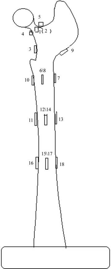
Schematic of electric resistance strain gauge distribution of femoral specimens. Measurement points 1, 2, 3, 4, and 5 were in the femoral neck area. Measurement point 4 was in the medial femoral neck at the upper 3 cm of the lesser trochanter; measurement point 3 was at the upper 1.5 cm of the lesser trochanter; measurement point 6 was at the transverse middle position of lesser trochanter; measurement point 8 was at the rear of measurement point 6; measurement point 7 was at the opposite side of the lower lesser trochanter; measurement point 9 was at the opposite side of the femoral neck; measurement point 10 was at the lower 1 cm of the lesser trochanter; measurement points 11, 12, 13, and 14 were stem tip positions of the anatomical prosthesis implantation group; and measurement points 15, 16, 17, and 18 were stem tip positions of the traditional prosthesis implantation group.