Figure 12.

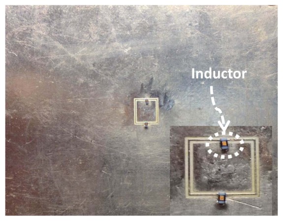
A CSRR after replacing the two narrow conducting bridges with lumped inductors. The red color indicates the highest current magnitude.

A CSRR after replacing the two narrow conducting bridges with lumped inductors. The red color indicates the highest current magnitude.