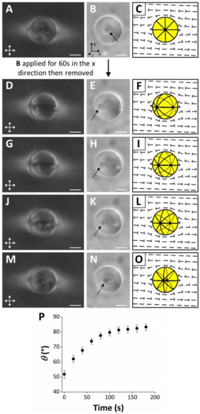
Fig. 3.

Rotation of 5CB droplets following application and removal of a magnetic field. (A, D, G, J, M) Crossed polars, (B, E, H, K, N) bright field (with arrows indicating the locations of boojums), and (C, F, I, L, O) schematic illustrations of a bipolar 5CB droplet in an aligned region of nematic DSCG. (A-C) Initial configuration of the droplet. (D-O) Configuration of the droplet after application of a magnetic field (B ∼ 0.3 T) in the x direction (see coordinate system in B) and removal at t = 0s. (D-F) Configuration of droplet at t = 0s, (G-I) t = 20s, (J-L) t = 40s, and (M-O) t = 120s. (P) Plot of the angle formed between the symmetry axis of the 5CB droplet depicted in D-O relative to the far-field director of nematic DSCG (θ) as a function of time following removal of the applied magnetic field. Error bars represent uncertainty in the calculation of θ associated with estimating the positions of the 5CB droplet center and one of the boojums of the droplet. Scale bars = 10 μm.
