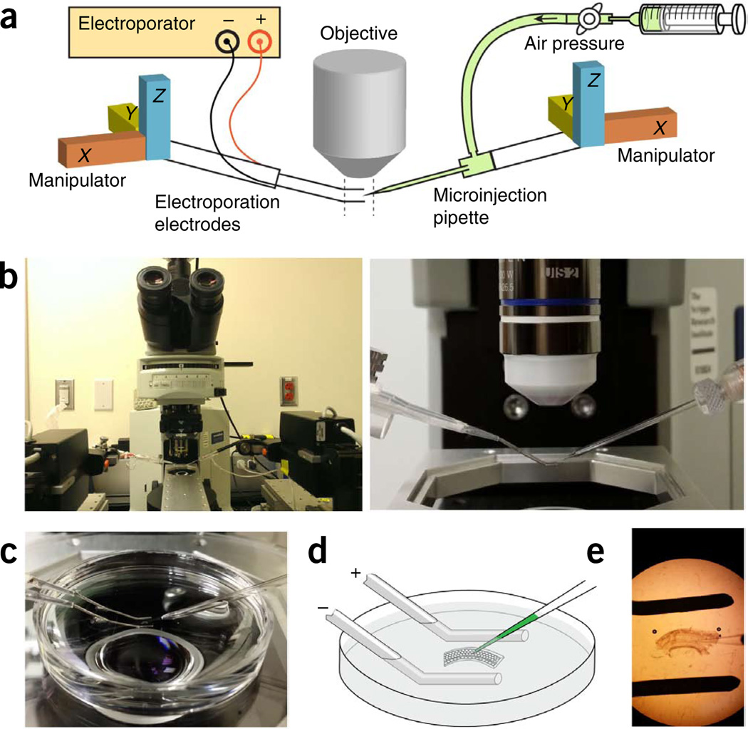
Figure 2.
Injectoporation setup. (a) Diagram of the injectoporation setup. (b) Left, image of the injectoporation setup. Note that the electroporator is not shown. Right, horizontal view of the electroporation electrodes and microinjection pipette. (c–e) Placement of the cochlear fragment, the electroporation electrodes and the microinjection pipette in a dish lid. (c) A photo view. (d) A cartoon view. (e) A microscopic view.

