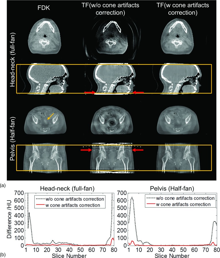
FIG. 7.
Cone artifacts correction. (a) Transverse view and sagittal view of the reconstructed volume images: head-neck and pelvis cases. Boxes in second and fourth row indicate the range of the volume in SI direction in current clinical practice. Within the box, two transverse slices as indicated by horizontal arrows are shown. The number of projections used in FDK and TF is 364 and 121 (head-neck) and 656 and 164 (pelvis), respectively. (b) Mean intensity differences of each slice between FDK and TF results before and after cone artifacts correction.

