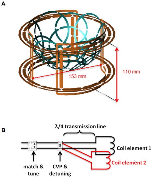
Figure 1. Overview of transmit and receive coil setup.
A) Rendering of transmit coil (in orange, i.d. = 153 mm, depth = 110 mm) with 16-channel receive array insert (in blue), and B) Schematic overview of FCE detuning circuitry utilizing λ/4 transmission lines to open-circuit each transmit coil element when diodes at the common voltage point (CVP) are biased.

