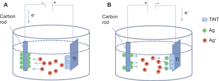
Figure 1.

Schematic diagram of AgO-deposited TiNT formation.
Notes: (A) Anodization process is shown. Ag ions moved toward carbon cathode, which was negatively biased with respect to Ti. Ag atoms were deposited on the cathode while TiNT were formed on Ti foil which was positively biased. (B) Ag electroplating process is shown. The polarity was reversed and Ag+ ions moved toward negatively biased Ti with respect to carbon cathode. Ag atoms deposited on the TiNT layer on Ti.
Abbreviation: TiNT, TiO2 nanotubes.
