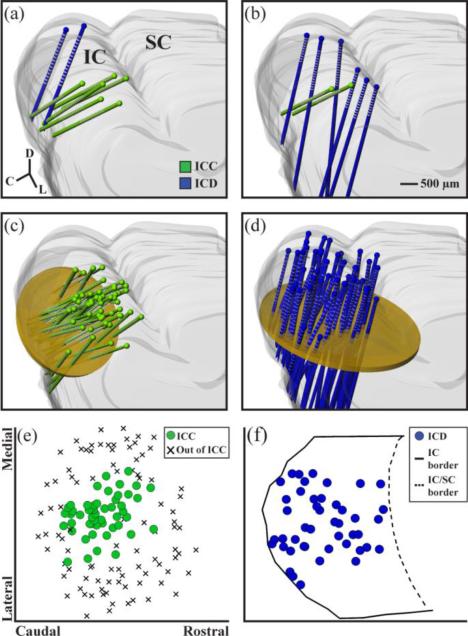
Figure 1.
Experimental protocols and array placements. In five experiments, one stimulation array placement (each array consists of two shanks) was made in the ICD and multiple recording array placements across the ICC (a). In seven experiments, one recording array placement was made in the ICC and multiple stimulating array placements in the ICD (b). All of the recording array placements (n=51 shanks shown in green) and all of the stimulating array placements (n=45 shanks shown in blue) were superimposed onto a single 3D reconstruction of the IC in (c) and (d), respectively. Planar cuts (shown in yellow) were made through the reconstructions orthogonal to the electrode array trajectories. Coordinates of the shanks through each plane are plotted as 2D maps in (e) and (f). For the recording locations in (e), each shank location was plotted along what is approximated as an isofrequency lamina that also includes recording locations identified as being outside of the ICC in order to show that we fully spanned the isofrequency dimension of the ICC. For the stimulation locations in (f), the borders of the IC were included on the horizontal plane in order to show that we fully spanned the rostral-caudal extent of the ICD. We were unable to sample the most medial portion of the ICD due to obstructive vasculature on the occipital cortex surface. The most lateral locations may include some portions of the ICX.

