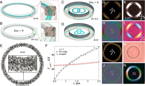
Fig. 1.

(A and B) Configurations with (A) a single s = 1 and (B) two s = 1/2 disclination rings, having isosurfaces of (A) and (B) shown in blue; (Insets) n(r) around the defects. (C) Hopf link and (D) trefoil T(3; 2) torus knot, known also as knot in the Alexander-Briggs notation, of half-integer disclination loops, with blue isosurfaces of . (E) n(r) in a plane of a torus with an escaped n(r) for . (F) Landau–de Gennes free energy, Eq. 1 (in excess over the free energy of the uniform nematic) as a function of at for the two structures. (G–J) Computer-simulated (G and I) POM and (H and J) 3PEF-PM textures of drops with (G and H) two defect rings and (I and J) escaped n(r). Linear polarizations of 3PEF-PM probing light (marked by red, blue, green, and pink double arrows) of four images used to obtain the superimposed textures shown in (H and J). (K–M) Optical micrographs obtained between crossed polarizer P and analyzer A, without (K) and with (L) an additional 530-nm phase retardation plate (blue double arrow depicts its low axis) and (M) without these optical elements. (N) Experimental 3PEF-PM texture obtained by overlaying images with polarizations of probing light at (red), (green), (blue), and (pink) and corresponding to H.
