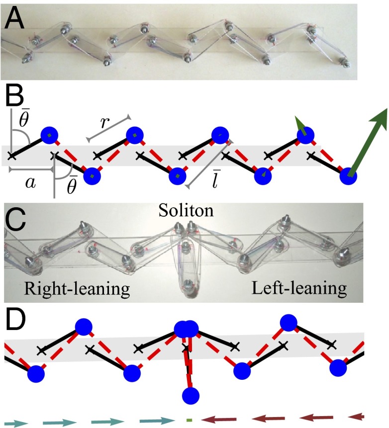
Fig. 1.
The chain of rotors in the flipper phase. (A) The translation symmetric system with constant. We show a linkage made from plastic and metal screws. (B) A computer sketch of the elastic chain (11): The masses are blue, rigid rotors are black, and springs are dashed red lines. The green arrows depict the amplitude of displacement of each mass of the edge-localized zero mode of the system. (C) A configuration of the linkage showing a soliton as a domain wall between right-leaning and left-leaning states. (D) A computer-simulated static configuration. The arrows beneath show the x projections of each rotor.

