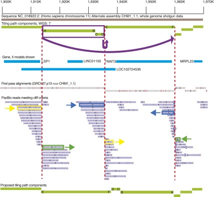
Figure 5.

Overview of the Chr 11 (NC_018922.2) 1.9-Mb region, exhibiting three alignment bins with a large number of PacBio “cliff” reads where the alignment coverage dropped off sharply. WGS component (light green lines) boundaries flanked by such reads are marked with red dashed lines. The ends of each component at the boundary are labeled with letters to show orientation. Pairs of alignments corresponding to three different PacBio reads are marked in yellow, green, and dark blue. These alignments overlap by < 10% on each of the reads. The split alignments for these three reads suggest that the two WGS components marked in purple should be inverted and translocated as indicated by the arrow at the top of the image. The other PacBio reads in these bins exhibit the same pattern of split alignments, which supports the proposed reordering and orientation of the WGS components. The bottom light green lines show a proposed tiling path with the orientation corrected; the letters indicate where each end of the initial tiling path components should be placed.
