
Figure 4.
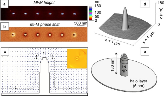
(a) Height and (b) phase shift MFM images of an array of six NPs deposited by FEBID. The 1 μm spacing between neighboring NPs excluded any magnetic interactions. (c) Cross-sectional OOMMF simulation of a single NP showing the (blue arrows) magnetic stray field, (black dashed line) the track of a virtual MFM probe in lift mode, and (inset) the corresponding MFM phase shift image obtained from OOMMF simulations. (d) 3D MFM height image of a NP and (e) the model used for the OOMMF simulations.