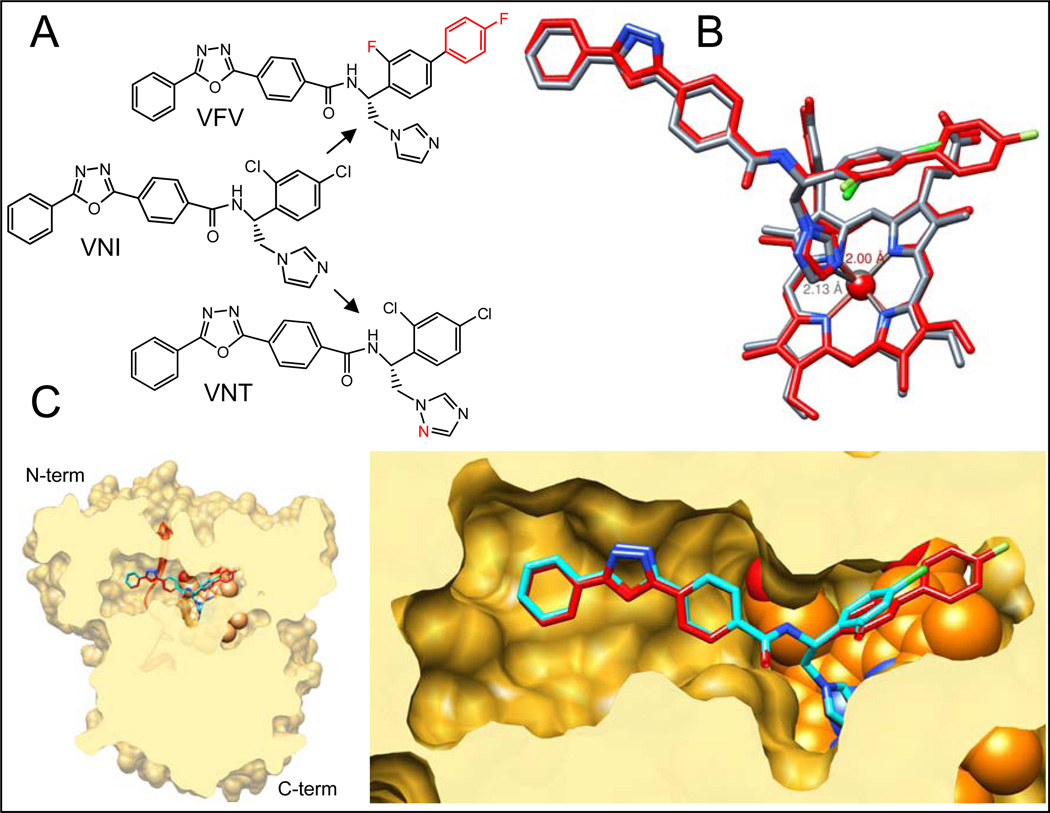
Figure 9. CYP51 structure based VNI scaffold development.
A. Structural formulas of VNI and its derivatives VNT and VFV. B. Superimposition of CYP51 complexes with VNT (grey) and VFV (red). The length of the Fe-N coordination bond in each complex is marked respectively. C. Slice through the binding cavity of CYP51 complexes with VNI (cyan) and VFV (red); surface representation. Left: overall structure, distal view. The SRS5 area (the C-terminal portion of helix K – β strand 1–4) is depicted as red ribbon. Right: enlarged view of the active site. The heme is shown as orange spheres.

