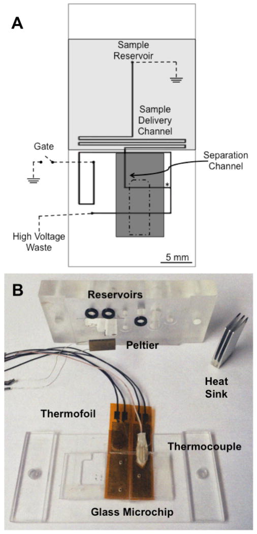
Figure 1. Schematic of microfluidic device indicating positions of the cooler and heater.
(A) The design of the microfluidic channels are shown as thick black lines and the electrical connections are shown as dashed lines (---). The reservoirs and channels are labeled on the figure. A thermofoil heater depicted in grey (
 ) was localized over the sample reservoir and sample delivery channel. A Peltier cooler was placed over the microfluidic device with its position shown in dark grey (
 ). The placement of the complementary thermocouple for the Peltier cooler is shown as an outline by a dash dot dash line (-•-). The detection point for the separations is shown as an asterisk (*). (B) The manifold used to house the microfluidic device with the thermofoils, the thermocouple for the thermofoils, the Peltier cooler, and the heat sink are shown. The thermofoils were attached below the device while the Peltier was attached on top. The black o-rings used to make the seals for the fluid reservoirs can also be seen.

