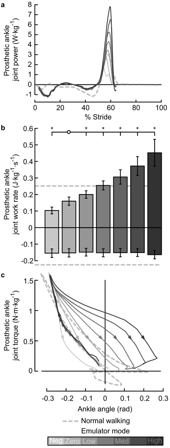
Figure 1. Prosthetic ankle mechanics calculated from on-board sensor data.

(a) Joint power. Lines indicate average trajectories for each condition, with darker lines corresponding to conditions with higher prosthesis push-off work. Dashed line indicates biological ankle joint power measured using inverse dynamics during Normal Walking. (b) Stride-averaged work rate. Positive and negative work were calculated separately. Error bars indicate inter-subject standard deviation, and *s indicate statistical significance. (c) Joint torque versus joint angle. Direction of motion indicated by arrows. Dorsiflexion curves are overlapping. The area inside each loop is the net prosthesis push-off work for that condition.
