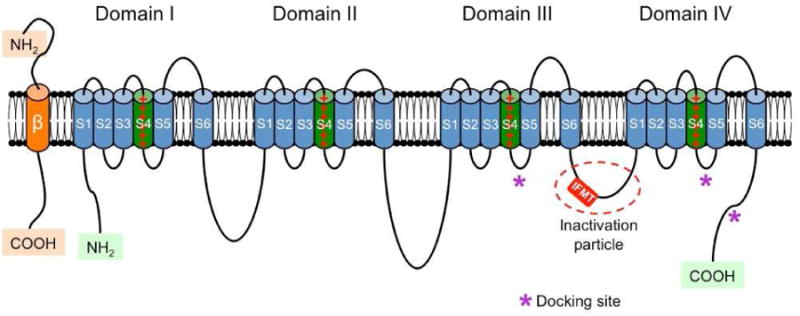
Figure 2.

Schematic representation of the α and β subunits of the voltage-gated sodium channel. The four homologous domains (I-IV) of the α subunit are represented; S5 and S6 are the pore-lining segments and S4 is the core of the voltage-sensor. In the cytoplasmic linker between domains III and IV the IFMT (isoleucine, phenylalanine, methionine, and threonine) region is indicated. This is a critical part of the “inactivation particle” (inactivation gate), and substitution of aminoacids in this region can disrupt the inactivation process of the channel. The “docking site” consists of multiple regions that include the cytoplasmic linker between S4-S5 in domains III and IV, and the cytoplasmic end of the S6 segment in domain IV (*). Depending on the subtype of β subunit considered, they can interact (covalently or non-covalently) with the α subunit (From Savio-Galimberti E, Gollob MH, Darbar D. Voltage-gated sodium channels: biophysics, pharmacology, and related channelopathies. Front Pharmacol. 2012 Jul 11;3:124. Doi:10.3389/fphar.2012.00124. eCollection 2012.
